Get in touch with Yibo Company


Marine Vibration Damping Floor: 8 Selection Inputs


A marine vibration damping floor controls vibration through a specified deck build-up. It’s chosen through 8 inputs: operating case, frequency, service temperature, deck construction, layer arrangement, load and mass limits, conditions of installation and required evidence. Thickness doesn’t indicate which treatment is most appropriate to address comfort on board.
For the naval architect, the question is whether the floor addresses the measured response. For procurement, it’s whether the same assembly is described in competing offers. A helpful selection brief connects these two questions prior to specifying material quantities.
What a marine vibration damping floor controls
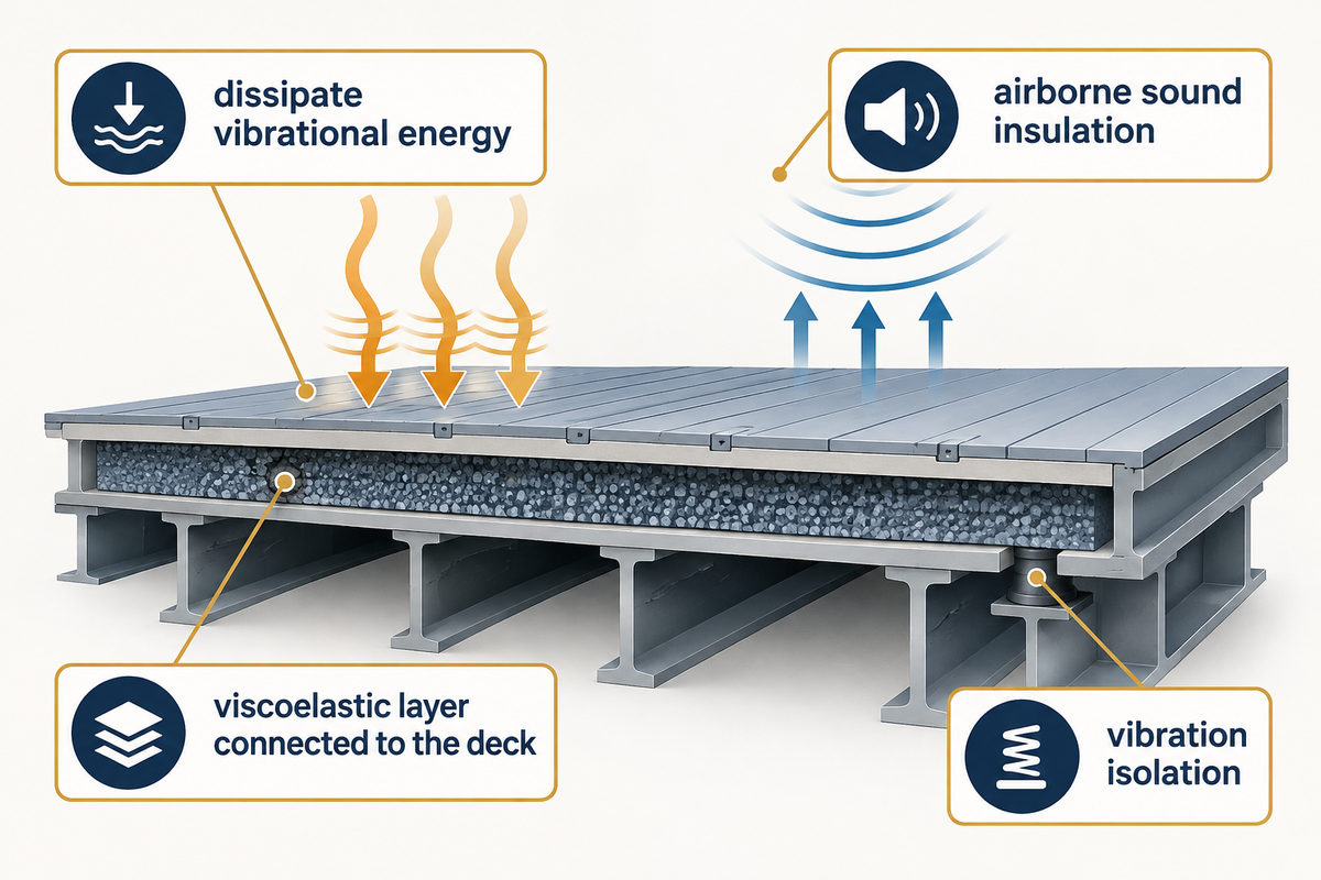
For shipbuilding projects, a damping treatment acts as a brake on flexing deck panels, thus dissipating some mechanical energy as the deck moves. A resilient floating floor, on the other hand, separates an upper floor from the supporting deck. Thus, sound absorption, airborne sound insulation, and vibration isolation require different selection criteria.
How does marine vibration damping flooring work?
A marine vibration damping floor is used to dissipate vibrational energy through deformation of a viscoelastic layer connected to the deck. The connection between the deck and the damping layer is important because deformation needs to reach the damping material. To dampen a deck panel vibration, the proposed layer needs to be connected to the structure that’s moving.
Noise and vibration can share a source while following different routes. An engine excites its mount and supporting structure; a panel can radiate airborne noise into a cabin. An appropriate acoustic lining can absorb sound inside the compartment while the panel continues to vibrate. Reduce the motion of the panel, and another transmission path may be audible.
Describe the problem in terms that can be observed. This may be a vibration complaint involving a narrow speed range, impact noise from foot traffic, or machinery noise in an adjacent space. A noise control proposal for a quieter environment should identify which of these changes and how it will be verified. Establishing early passenger comfort goals provides the designer a measurable objective.
Marine Damping Selection Inputs: the selection brief
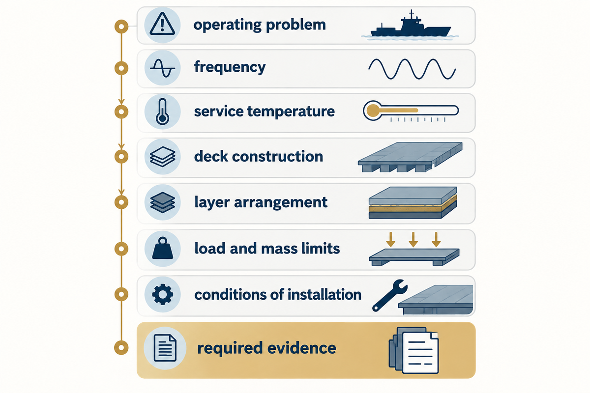
The Marine Damping Input Ladder can transform eight input groups into a workable selection. First, state the operating problem, then define the assembly and limits, and end with test evidence for acceptance. Each row assigns an owner; unanswered questions require resolution by a particular person.
| Input | Record in the brief | Decision it controls | Owner |
|---|---|---|---|
| 1. Source and operating case | Engine, propeller, pump or footfall; speed, load and vessel condition | Which excitation the treatment must address | Owner / machinery engineer |
| 2. Frequency spectrum | Peak frequencies in Hz, measurement points, direction and response units | Relevant material data and assembly response | Acoustical specialist |
| 3. Service temperature | Expected deck temperature range in °C during operation | Damping data at the intended operating conditions | Owner / designer |
| 4. Deck construction | Steel or aluminium, plate thickness in mm, stiffener layout and supports | Panel flexibility and boundary conditions | Naval architect |
| 5. Layer arrangement | Every layer, bond, finish, perimeter and penetration detail | Damping, isolation and acoustic transmission paths | System supplier / designer |
| 6. Load and mass limits | Distributed and concentrated loads; permitted kg/m²; furniture and equipment | Support selection, deflection and weight allowance | Structural designer |
| 7. Installation conditions | Substrate, primer, application temperature and available cure window | Whether the yard can reproduce the specified construction | Yard quality lead |
| 8. Required evidence | Vibration and acoustic targets, applicable approval scope, test configuration | Proposal comparison and acceptance | Owner / approval authority |
A quotation may proceed with an open item, provided it states the assumption and who must close it prior to release. For example, price a defined construction while the specialist confirms the operating spectrum, and keep that price tentative until the spectrum is reviewed. Don’t treat an unknown frequency as a pass.
Candidate build-ups can be identified using the acoustic flooring constructions page after these inputs are combined. A material family can be a starting point for this comparison, not a substitute for the deck drawing.
Diagnose source and transmission path before choosing a floor
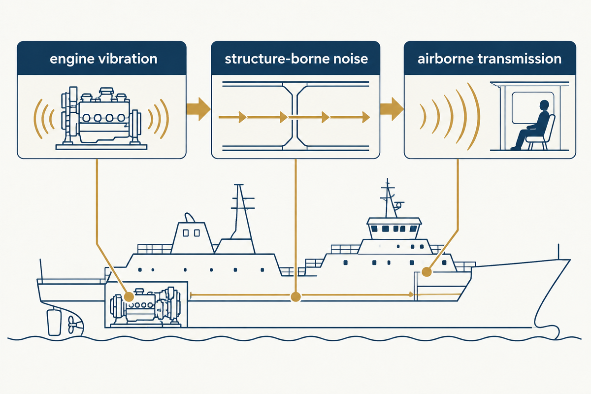
Separate the responding surface, route through the vessel, and source before choosing a floor. The same cabin complaint can occur with machinery support, a flexible deck or airborne transmission through an enclosure. Record repeatable operating conditions to compare before and after measurements of the same problem.
To improve the comfort of a hypothetical passenger cabin that becomes uncomfortable only over a narrow engine speed interval, record the engine speed and occupied measurement location first. An attractive rubber mat quotation may be easy to obtain, but it leaves the speed-related excitation unresolved. The machinery engineer should determine if the complaint follows engine operation, propeller loading or something else. The acoustical specialist should then compare deck and cabin floor responses. The next most useful action for procurement is to hold the material order for the treatment until that path is identified.
Structure-borne noise can be transmitted through the hull and supporting members. This route also explains the need for a different treatment for structure-borne sound than sound moving through the air. Eliminating one route doesn’t always eliminate the other, which can still occur through partitions, pipes or attachments. Wider compartment acoustic planning should identify the requirements for sound insulation of the surrounding areas.
A small, fast boat needs a separate shock question. The UK’s Maritime and Coastguard Agency Guidance distinguishes between low speed vibration and wave impacts: standing on soft foam or rubber flooring may help with the former, while instability can add fatigue.
“these materials do not mitigate the effects of wave impacts”
Match the floor system to frequency and deck construction
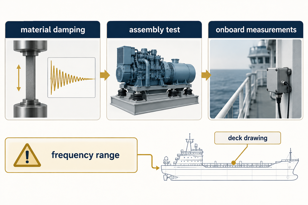
Match a damping proposal to frequency, temperature, and the deformation that will occur. Material properties help describe a layer; an assembly test describes a particular build-up; onboard measurements describe a vessel under certain conditions. Keep these levels separate when comparing offers, despite reports using the word “vibration.”
ASTM E756-05(2023) presents measurements of material damping over the frequency range of 50-5,000 Hz, and the useful temperature range of the material. It discusses the loss factor and modulus using vibrating beam specimens. These properties can be used to inform an engineering model within the framework of the assumptions of the method; they do not provide an assurance of a reduction in cabin noise.
ISO 20283-5:2016 addresses vibration habitability in normally occupied passenger and merchant ship spaces, using overall frequency-weighted root-mean-square evaluation over 1–80 Hz. Its public scope concerns voyages of 24 hours or more. ISO confirmed that edition in 2026; confirmation is not a new technical edition.
These frequency bands respond to different questions. A material test method can’t simply replace the project’s shipboard acceptance procedure. Compare only test bands of interest, temperature, and layer arrangement. Reporting a headline result doesn’t allow a comparison.
A measured ship case: the floor joined the deck response
Rognoni and colleagues’ 2024 study of the research catamaran Mintis investigated six propeller operating conditions. A coupled deck-and-raised-floor mode near 14.3 Hz helped explain the measured response. The vessel’s raised floor sat 300 mm above a 6 mm deck; these are case details, not suggested floor dimensions. For this particular low-frequency problem, the authors found additional viscoelastic material unhelpful and a floating floor impractical. Their proposed structural changes remained future work. For buyers, the case shows why a deck drawing and measured operating spectrum belong in the enquiry: an isolated material result can’t describe every coupled structure. It also cautions against describing a proposed reinforcement as a proven repair. An offer for a similar symptom should explain how the selected assembly addresses the measured mode before attaching a performance commitment.
Read the condition alongside the value
Loss factor without temperature is an incomplete comparison. So is dynamic stiffness of a resilient pad without the load condition for which it was measured. Ask if a laboratory specimen contains the proposed deck along with the bonding layers, upper mass and supporting details. A change to any of these items requires an engineering assessment of its impact.
A 2015 study by Caniato and colleagues examined dynamic stiffness, compressibility and creep in 20 resilient layers for building floors. Its findings support asking about sustained loading and material conditioning, but don’t establish a marine service life.
Compare damping, resilient underlay, and floating floor systems
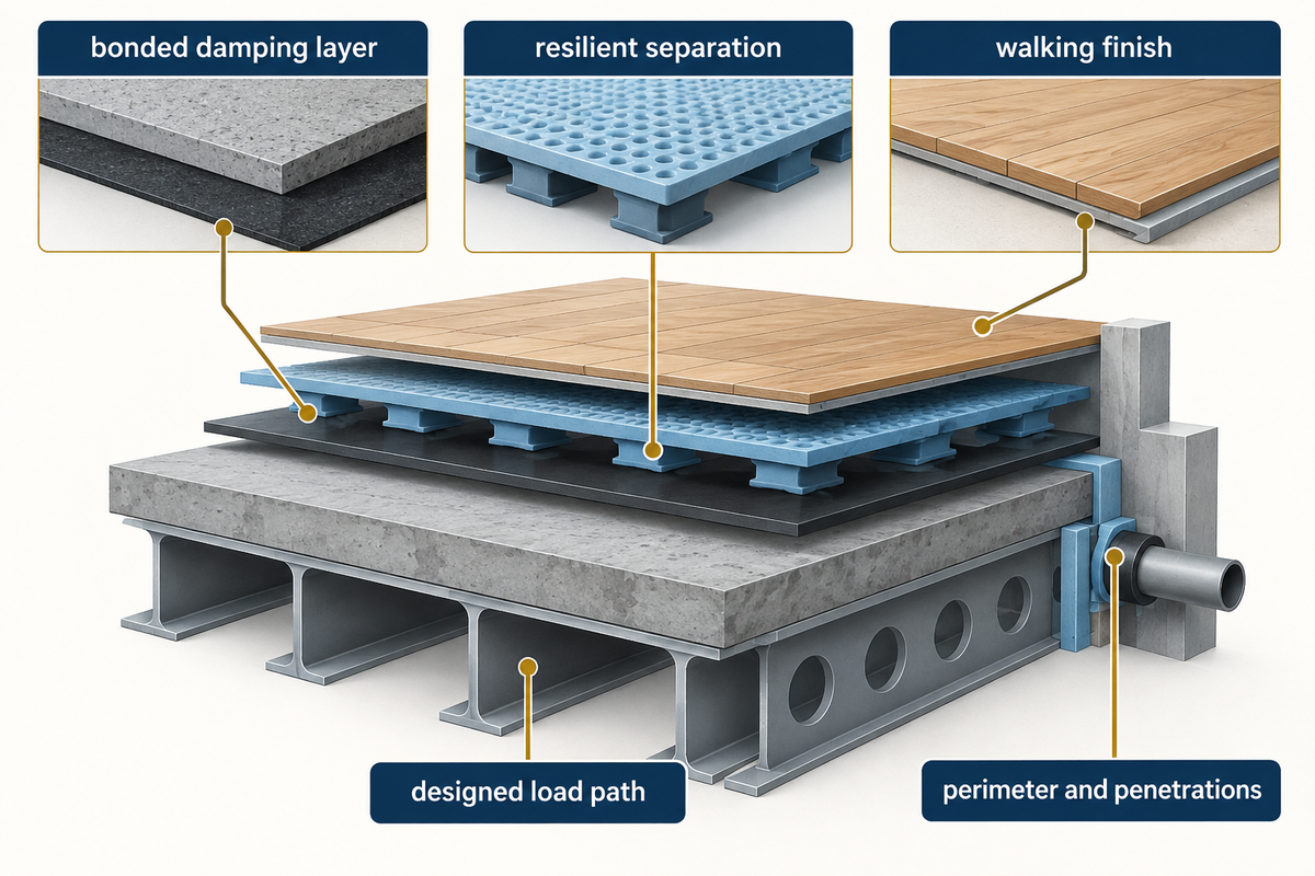
Comparing prices or thicknesses of various materials shouldn’t happen before comparing their underlying treatment mechanisms. For example, a bonded damping layer addresses structural deformation, while a floating floor uses resilient separation. A space lining is used for addressing internal sound. A finish may improve footing without performing the function required for the project.
| Item or measure | Primary question | Evidence to request |
|---|---|---|
| Bonded damping coating | Can panel deformation engage the layer? | Material data and defined substrate / layer construction |
| Constrained damping build-up | How do deck, damping layer and constraint work together? | Bonded assembly details and relevant response data |
| Resilient underlay | How does the layer behave under the imposed load? | Dynamic stiffness, compression and conditioning data |
| Floating floor | How is the upper floor isolated from the deck? | Full assembly, supports and perimeter details |
| Machinery isolator | Can excitation be reduced at its source connection? | Machine loads and mounting design |
| Acoustic barrier | What airborne transmission path is addressed? | Assembly sound insulation results |
| Sound-absorbing lining | What sound field inside the compartment is addressed? | Absorption data and installation arrangement |
| Soft walking finish | Is the objective footing, footfall or comfort? | Relevant surface / assembly tests |
| Structural modification | Does deck stiffness or coupling dominate? | Structural assessment and response verification |
Do marine vibration damping floor mats work?
Floor mats are appropriate to address a defined contact or footfall problem with the construction for which they’ve been tested and evaluated. An unsecured mat isn’t a general solution for vibration carried through a ship’s structure. Determine if the mat is a walking finish, a resilient support or part of a bonded damping system before buying it.
A rubber or polyurethane layer used as vibration isolator material needs a designed load path. “Anti-vibration” on a product label doesn’t indicate natural frequencies or lateral constraint or the allowable load. Not every foam sheet can be treated as an engineered support.
For a floor intended to float, examine edge strips, fixings and penetrations on the proposed drawing. Rigid connections may transmit motion across the intended separation. Check how the detail will decouple the walking surface from attachments that bridge it. To review upper-floor support details, compare the complete assembly, including its finish and perimeter.
Set weight, thickness, and headroom limits
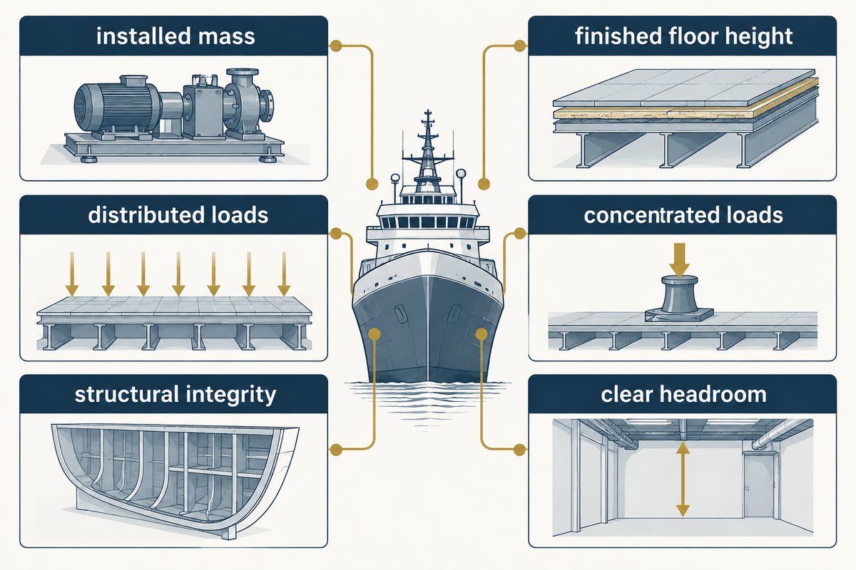
Set an allowable installed mass and finished floor height before assessing acoustic options. Count every added layer, including adhesive, levelling material and finish, and keep distributed loads separate from concentrated loads. A lightweight intermediate layer may still belong to a heavy complete assembly. Compare total values on the same basis. Protecting structural integrity requires the responsible designer to review the added loads.
A material quantity calculation, with its boundary stated
Weber’s published marine VEM PU 1 data gives a consumption of 1.35 kg per mm per m² and a layer range of 1–4 mm. For a hypothetical 100 m² area with a thickness of 2 mm, the consumption would be 1.35 × 2 = 2.70 kg/m²; 2.70 × 100 = 270 kg before waste. This example is for illustrative purposes only, to show a materials quantity, not the complete floor’s installed mass or a Yibo product definition.
To answer that hypothetical question, procurement can ask each bidder to separate the intermediate layer quantity from the total assembly mass. The naval architect needs the total assembly mass to determine the weight allowance for the vessel. Yard staff also need weight allowance for surface irregularity and the application limits specified. If one quote includes the upper plate and the other quote stops at the damping layer, comparing their kg/m² values would favor the incomplete offer. Resolve the difference in scope before using the calculate added deck mass tool.
Headroom also needs a project specific check. For accommodation within its scope, UK MSN 1844(M) Amendment 1 specifies 203 cm clear headroom where free movement is required. There are also permitted exceptions and reductions. Apply the vessel’s requirements rather than treating the UK headroom figure as a universal floor-thickness allowance.
Verify fire, class, and acoustic evidence
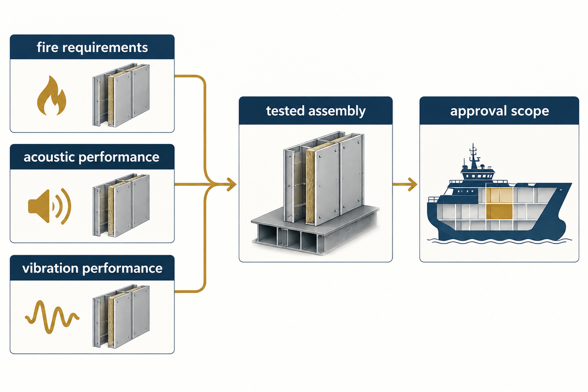
Request evidence for fire requirements, acoustic performance, and vibration performance individually and match each to the stated construction. A certificate’s product name, holder, assembly and conditions must correspond to the proposal. The owner and the applicable approval authority need to resolve the scope of the required review, prior to the release of the material from the yard for installation.
The Unmatched-Test Trap occurs when a credible test answers a different question. A laboratory sound insulation result may help assess airborne transmission but say little about the measured structural response. A material loss factor characterizes damping behavior under test conditions; it doesn’t define the final state of the ship’s noise levels.
Construct an evidence schedule with requirements, document IDs, tested assembly, and proposed assembly columns. In the difference column, provide an explanation for any deviation from the scheduled assembly. If the supplier changes the adhesive or the upper layer, capture the change in the schedule. Accept a lower price only if the deviation is acceptable for the requirement.
Keep laboratory metrics separate. Transmission loss, insertion loss and onboard sound pressure levels are different metrics and should be evaluated under the conditions of the test. Compare like with like using the expert’s specified acceptance criterion. A single noise reduction number without the frequency band and measurement arrangement is a poor basis for a purchase commitment. Define how the treatment reduces noise under the specified test conditions. Don’t make a promise to soundproof.
Plan substrate preparation, installation, and inspection
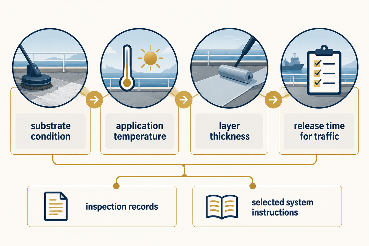
Installation should be planned in accordance with the instructions for the layer’s product, as well as tests on the assembled version. Record the condition of the substrate, compatibility of the primers used, application temperature, layer thickness, and release time for traffic. Service temperature and application temperature are two different inputs. A window for yard installation doesn’t establish damping performance over the vessel’s operating temperature range.
Sikafloor Marine VEM provides an example of how specific these controls can be. Its published application data specifies 1.5–2 mm, a maximum layer thickness of 2 mm and a substrate temperature of 5–30 °C. At 23 °C and 50% relative humidity, it lists about 30 minutes of working time and about 12 hours before walking. These are the stated conditions of this product, not a shared marine-floor cure schedule.
In a hypothetical refit, the yard wants to reopen a passage immediately after applying a wet layer. The material buyer first needs to compare the required access time with the chosen product’s release conditions. If access conflicts can’t be resolved by dividing the passage into work zones, then assuming a shorter cure time isn’t an allowable solution. The site quality lead needs to record application temperatures and times, identify the person releasing each zone, and coordinate subsequent trades so their fixings do not alter the approved detail. A mis-selected, less expensive material may require a different work sequence.
Check primers against the substrate, especially against aluminum or a zinc-primed surface. Follow the selected system’s instructions for any tie coat. The damping coating application controls guide provides more details about the coating stage.
Follow the drawing during inspection from the prepared deck to the finished surface. List batches and layer thicknesses, photograph interfaces before covering them, and check edge and penetration details. In accommodation subject to the UK notice cited herein, provisions for secure footing, cleaning, water impermeability and joints of walls without crevices are also covered. Acoustic performance can’t be purchased separately from a usable completed floor.
Use the Source, Path, Evidence Matrix to make the choice
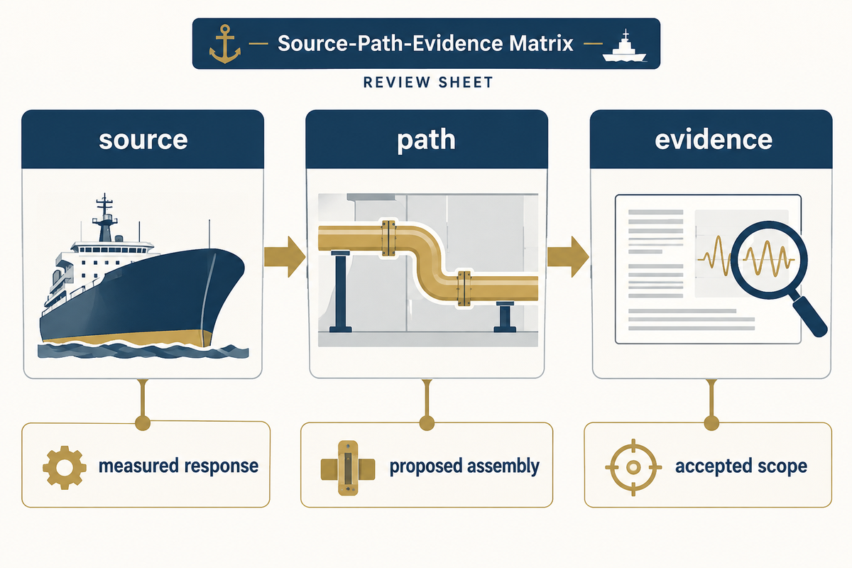
The Source-Path-Evidence Matrix compares proposals against the problem they address and the proof they provide. Use it as a review sheet, not a performance score card. Each row specifies an action to supply a missing input, direct the proposer to the person responsible for accepting the proposal, or both.
| Observation or proposal | Missing connection | Next decision |
|---|---|---|
| Complaint appears at one operating speed | Source to excitation frequency | Measure the operating spectrum before selecting the layer |
| Deck and upper floor respond together | Coupled structural behavior | Ask for assembly response assessment |
| High material loss factor offered | Temperature and frequency match | Compare curves at the project conditions |
| Floating floor supported by generic pads | Pad load and dynamic stiffness | Request support layout and load-specific data |
| Noise reduction stated without a method | Metric and test configuration | Request the report before ranking performance |
| Thin layer presented as a light floor | Complete assembly mass | Obtain the full kg/m² build-up |
| Product certificate supplied | Proposed assembly and applicability | Close deviations with the approval authority |
| Cure window conflicts with access | Material release and yard sequence | Revise the work sequence or candidate system |
| Finished installation differs at edges | Intended isolation / damping detail | Inspect and resolve the drawing deviation |
Assess two alternatives for the same cabin area. One provides a low bid and a Material Data Sheet (MDS). The other provides an assembly drawing, total mass, and a report with stated test conditions. The second is more reviewable; however, the conditions still need to align with the brief. Ask the first bidder for the same type of return, then compare the conditions and accepted scopes. The finance team can assess the price difference without confusing savings with work omitted.
There’s often an interdisciplinary hidden constraint as the missing connection between the disciplines: A spectrum without a deck model, a certificate without the offered layers, a product instruction without a workable yard sequence. Each unresolved row should be assigned to its owner with a release condition.
Request-for-quote checklist and vendor handover
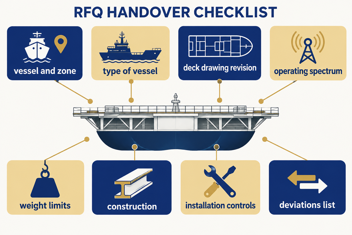
Send the eight-input brief with the related deck drawing and request a line-by-line return. The vendor should give the construction, quantities, total mass and installation controls and evidence offered. A deviations list shows what assumptions the vendor will make before procurement compares prices or the yard commits to an installation sequence.
| Parameter | Recommended range / requirement | Why it matters | How to verify |
|---|---|---|---|
| Operating frequency | Measured project bands in Hz | Defines the response to address | Operating-case spectrum |
| Service temperature | Project deck range in °C | Locates relevant damping data | Owner’s operating brief and material curves |
| Layer construction | Named materials and specified mm per layer | Defines the quoted assembly | Signed build-up drawing |
| Mass and loading | Within approved kg/m² and load limits | Protects the vessel weight and structural budget | Complete mass schedule and structural review |
| Installation window | Selected product’s temperature and cure conditions | Determines yard sequencing | Application method and inspection records |
| Acceptance | Project-specific test and approval requirements | Makes offers comparable | Report schedule and resolved deviations |
For Yibo marine flooring, specify the compartment, type of vessel and drawing revision. Provide measured vibration information if available, and identify the other open-ended engineering questions. A good return package tells the designer what can be evaluated and tells the yard what has to be controlled during installation.
Prepare your marine damping floor brief.
Share your deck build-up, operating spectrum and weight limits for a project enquiry.
Send Your Selection Inputs
Frequently asked questions
What is a marine vibration damping floor?
A marine vibration damping floor is a specified shipboard floor construction intended to reduce a defined vibration response through damping, sometimes alongside resilient separation.
The term covers different constructions, so the enquiry should identify the working layer and its role. A bonded damping layer, a floating floor and a soft walking finish are not interchangeable. Describe the deck, upper layers and intended response together; then request evidence for that construction under conditions relevant to the vessel.
Are marine vibration damping floors worth it?
A damping floor is worth evaluating when measurements connect the complaint to a response the proposed construction can address.
The financial comparison should include the complete build-up, installation work and the yard access schedule. A low material price can omit the layer or preparation needed to reproduce a tested assembly. Conversely, a sophisticated floor may be a poor purchase if the dominant problem is a machinery connection elsewhere. Establish the path first, then compare accepted scopes and their total costs.
Which marine vibration damping floor is best?
The best candidate is the construction that fits the measured frequency and operating conditions while meeting the vessel’s mass, height, installation and approval requirements.
There is no single material ranking that resolves those constraints for every ship. Compare proposals using the same deck drawing and operating brief. Give each supplier the same response schedule, then have the relevant specialist resolve differences in the tested assembly, support loading and installation detail before choosing on price or promised acoustic performance.
What inputs should be in a marine floor RFQ?
A marine floor RFQ should contain the operating case, spectrum, service temperature, deck drawing, proposed layers, loading limits, installation conditions and acceptance requirements.
Attach measurement locations and units so that the spectrum can be interpreted. Identify fixed equipment and concentrated loads, not just the floor area. Mark drawing revisions and separate the desired construction from any approved existing detail. Where an input is pending, name the responsible party and the decision that depends on it. Ask bidders to list assumptions in their return rather than silently filling the gap.
Are marine vibration damping floors safe?
Safety depends on the selected assembly, its application and the vessel’s applicable requirements, including structural, fire and finished-surface conditions.
Review the specified construction and installation controls with the responsible project parties. Soft flooring intended for vibration comfort should not be treated as protection from wave impacts on small vessels. Changes to layers or supports need the same disciplined review as the original proposal.
Can a floor treatment solve engine vibration by itself?
A floor treatment can address part of an engine-related response, but it may leave excitation at the machinery support and other transmission paths unresolved.
Compare source operation with deck and compartment measurements. If the main path lies elsewhere, the appropriate intervention may involve the machinery mounting or structure, followed by a floor treatment only where justified.
What should a vendor return with the quotation?
A vendor should return a defined assembly, quantity and mass schedule, installation method, evidence schedule and a clear list of deviations from the enquiry.
Require product names and layer dimensions that can be traced to the drawing. Separate material consumption from complete installed mass. The evidence schedule should state the tested configuration and conditions; the installation method should identify primer, substrate and curing requirements. Procurement can then compare equivalent scopes and route technical exceptions to the designer before release.
References & Sources
- ASTM E756-05(2023): Measuring Vibration-Damping Properties of Materials public scope and method summary.
- ISO 20283-5:2016: Ship vibration habitability public scope and current edition status.
- Rognoni et al. (2024), Application of Modal Analysis for the Vibrational Comfort Investigation on Board Ships: a Case Study Journal of Marine Science and Application.
- Caniato et al. (2015), Time-depending performance of resilient layers under floating floors public research abstract; building-floor scope.
- MCA MGN 436 Amendment 5: Whole-body vibration on small vessels section 5.5.4.
- MCA MSN 1844(M) Amendment 1: Crew accommodation applicability, headroom and flooring provisions.
Commercial marine flooring systems
Plan the deck build-up before the workfront is released.
Yibo manufactures commercial marine flooring systems in Suzhou for vessel projects that need a coordinated deck-covering, resin-floor, or acoustic-floating-floor build-up.
Review marine deck covering systems, marine resin floor systems, and marine acoustic floor systems against the vessel area and planned application sequence.
Project enquiry
Give the engineering team the inputs that shape the system review.
Include the vessel area, substrate or deck condition, intended floor build-up, fire or acoustic target, and project schedule so the enquiry can begin with the relevant deck constraints.
Send Your Deck Schedule