Get in touch with Yibo Company


Marine Resin Flooring Systems for Commercial Vessels
Yibo Marine Systems supplies our marine resins for shipboard installations. We have flooring solutions for differing installation requirements and surface qualities. Compare our products the E60, S22 and S20 using the intended function, then supply the vessel’s area, substrate and expected finish for project evaluation.
Supply the deck drawing showing the arrangement and the substrate build-up so your enquiry includes all construction details.
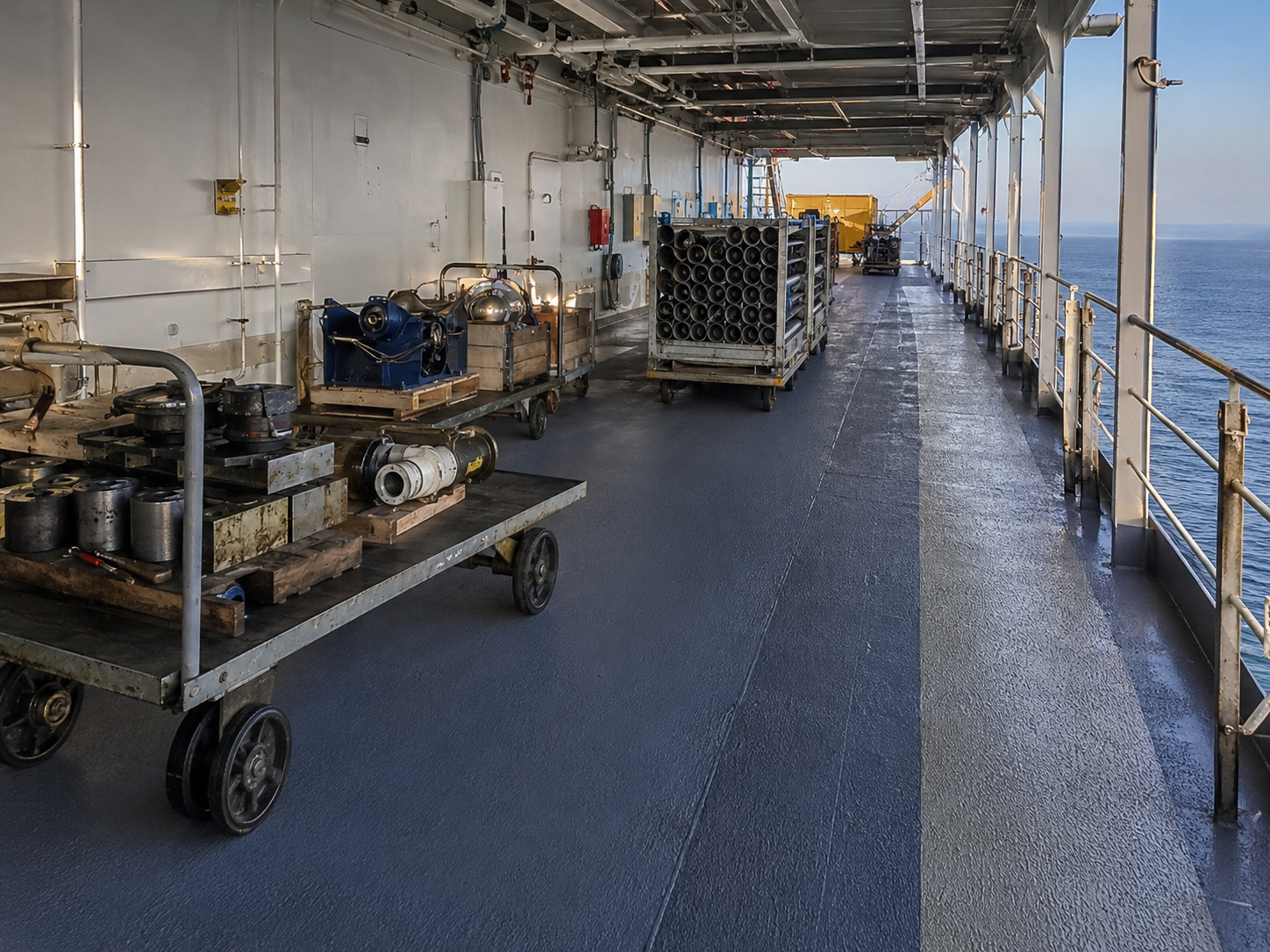
E60 floor covering
5 mm certificate build-up
S22 self-leveling finish
2 mm certificate specimen
S20 primary covering
10 mm nominal certificate thickness
Epoxy and Polyurethane Marine Flooring Systems
Our products separate the installation’s top most cover layer from its substrate below it, and any isolated resin naming will not clarify the product specification for covering, substrate resistance and fire-tested purpose in any installation of these non-interchangeable resin products.
Marine Epoxy Floor
Model: E60
E60 combines an epoxy resin and coloured-sand layer with a polyurethane varnish. Its certificate describes the combined floor covering, so an epoxy-versus-polyurethane comparison must account for both layers.
View E60 Specifications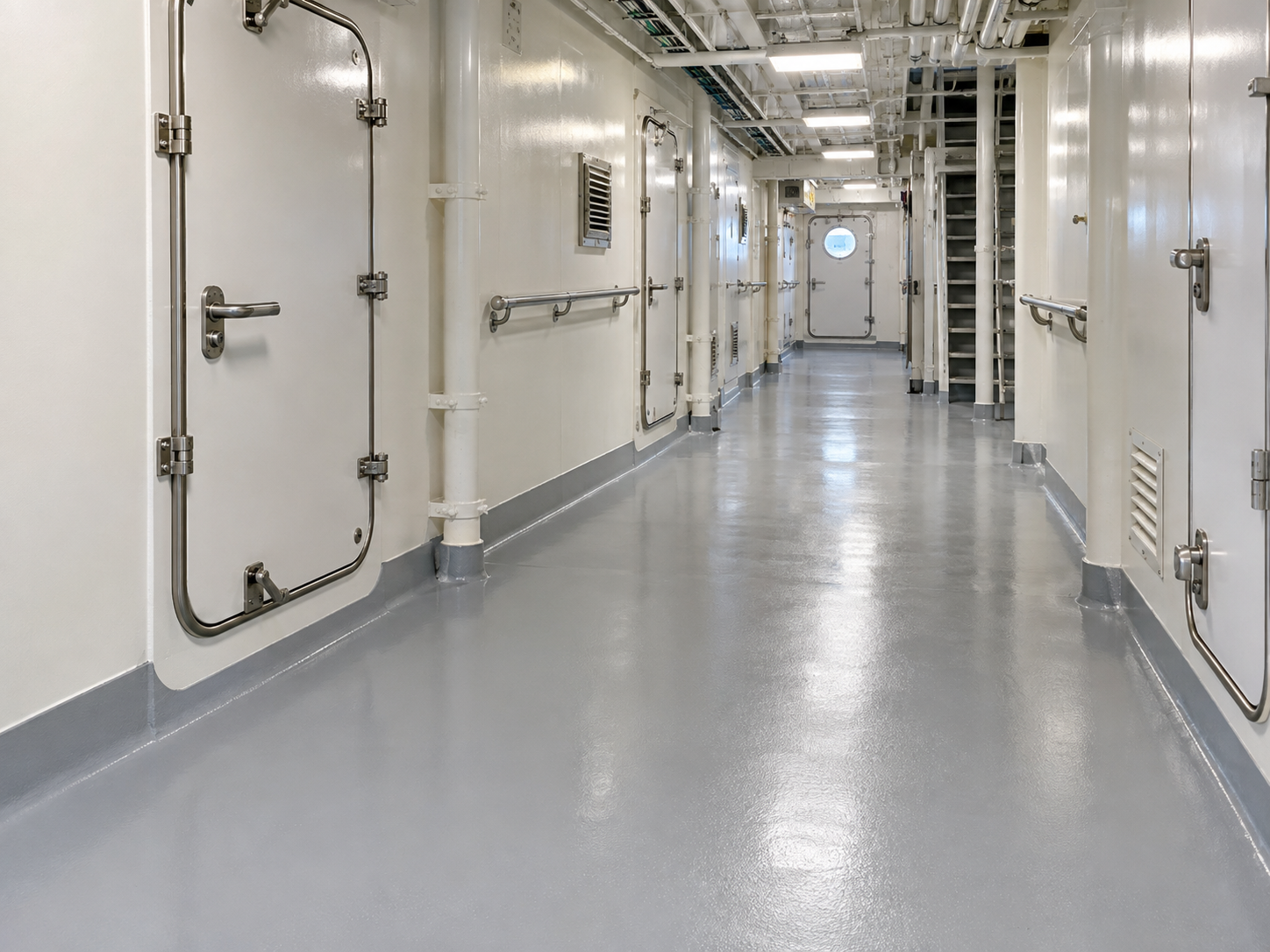
Marine PU Floor
Model: S22
S22 is a polyurethane self-leveling deck covering. Its documented specimen is a thin finish on steel; review the supporting construction and the specified surface duty before selecting this route.
View S22 Specifications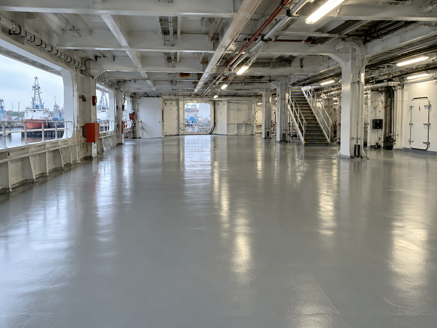
Primary Deck Covering
Model: S20
S20 combines a resin binder with lightweight aggregate for a primary deck-covering role. It belongs in the build-up review, rather than a direct comparison based only on the wearing-layer thickness.
Substrate, Primer and System Build-Up
For installation, the substrate is paramount; the foundation is the first stage and any damage beneath it will affect the integrity of any fix if it is only at the finishing stage, where the structural flaws below may result in the incomplete work if the initial underlying structural problems haven’t been attended to and confirmed beforehand for material inspection to suit your choice.
Review Input
Steel or other material, condition and movement
Decision before installation
Separate structural repairs from surface preparation.
Review Input
Material identity, thickness and bond condition
Decision before installation
Determine removal or retention from the proposed system instructions.
Review Input
Exact product and preparation method
Decision before installation
Check compatibility and the permitted certificate construction.
Review Input
Required level, thickness and supporting assembly
Decision before installation
Confirm its function before selecting the wearing finish.
Review Input
Resin, aggregate, colour and texture
Decision before installation
Keep all layers tied to the selected product specification.
Review Input
Drains, thresholds, coves and movement joints
Decision before installation
Resolve termination and seal details without obstructing drainage.
Our company standard application of the installation of E60 is the build-up composed of the colored sand layer of about 4.8 mm and lacquer of about 0.2 mm. Should there be an alternative with respect to any coating, an accompanying binder substance, a foundation product or similar components, the said alteration shall be qualified as a reconstructional amendment.
Whether the surface finish is flat or sloped affects functionality, not only by description; a floor will drain according to its designed fall, so the fall or slope shall be illustrated on the floor plan drawing and neither the description for leveling the finish nor mention of the plastic material’s fluidity determines the flow characteristics on completion.
For concrete, record moisture conditions and the proposed primer or barrier; for steel, record corrosion preparation and the accepted coating underneath. A resin coating is not a substitute for repairing the substrate. Match the base and adhesive to the specified construction.
Wet-Area, Chemical and Decorative Surface Duties
The appearance and installation specification shall support the intended use; a durable floor depends on the entire construction, not only one aspect, while a chemical-resistant finish requires identification of the substance, concentration, temperature and exposure time for any spill.
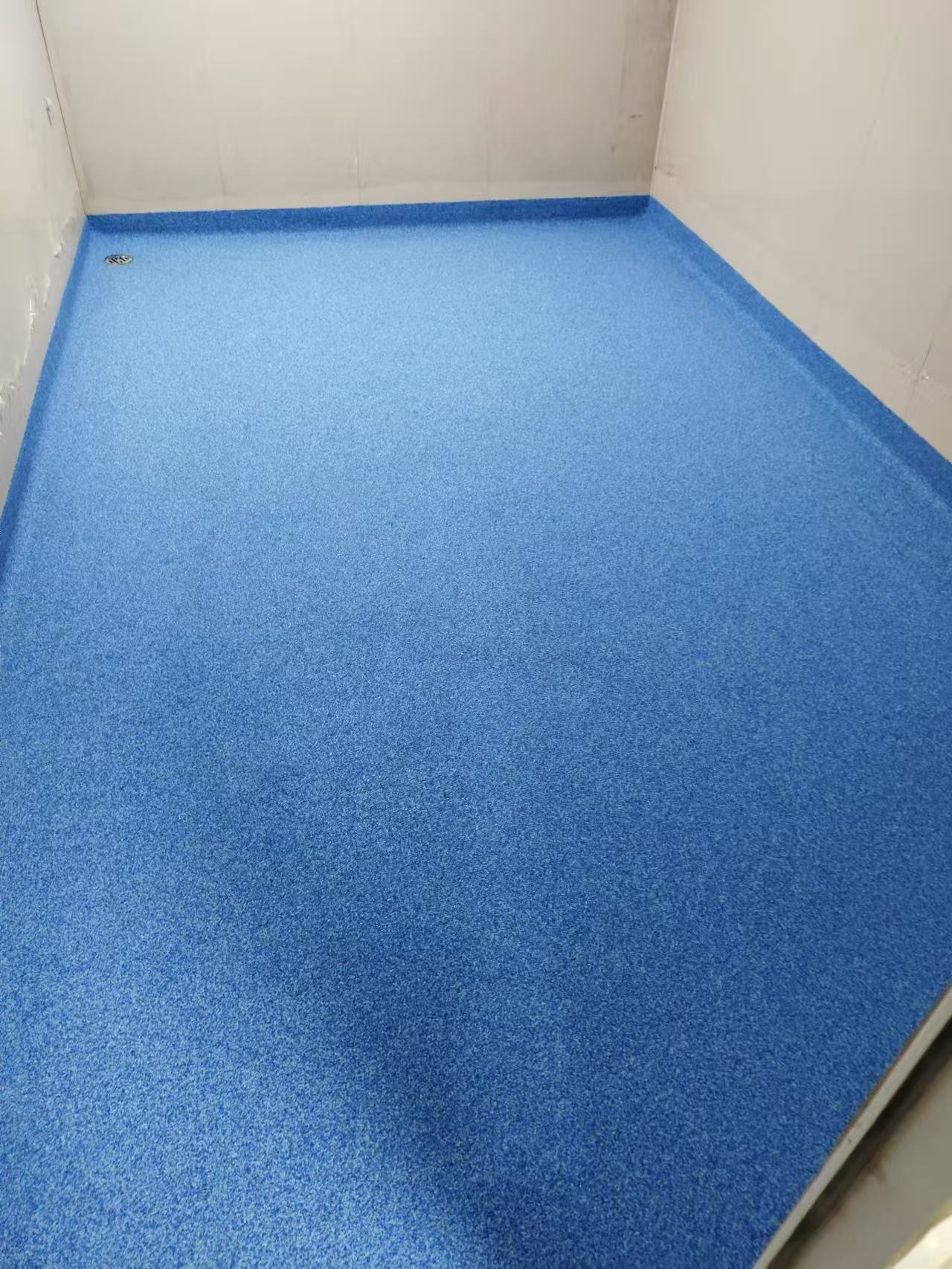
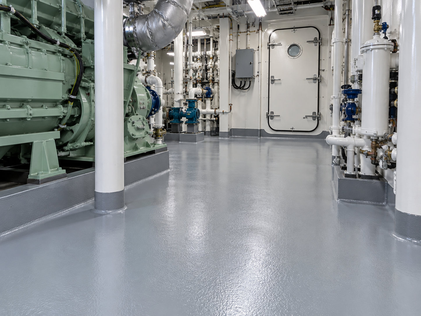
Blue finish with perimeter coves and a drain. Include these interfaces in the area drawing.
01
PARAM // 01
Wet traffic and cleaning
Define likely water, oil or food contamination and the cleaning routine. Select the slip-test method and test conditions for the intended surface; a fire result does not establish wet slip resistance.
Analysis Targets //
02
PARAM // 02
Abrasion and local loading
Identify trolley routes, wheel contact, repeated turning and impact locations. Use the product’s wear and strength indices within their stated methods, rather than converting them into an unsupported service-life promise.
Analysis Targets //
03
PARAM // 03
Colour and texture
Review the intended colour, aggregate and surface profile together. The E60 certificate identifies its specimen colour and construction, so a decorative change also needs a scope check.
Analysis Targets //
04
PARAM // 04
Exterior exposure
Open decks add UV exposure, temperature changes and weather during installation. Identify these conditions in the inquiry; the word polyurethane alone does not establish UV resistance for a particular finish.
Analysis Targets //
Surface treatment includes cleaning procedures to prevent surface impurities from creating slip hazards during use; contaminants, no matter how subtle, can render the surface slick, so the chosen coating, drain features, cleaning approaches and their operation procedures and access arrangements must work together.
For cruise ship flooring, distinguish interior corridors from washdown compartments and exterior working decks. The property required to withstand a chemical splash differs from the resistance needed under repeated trolley traffic; submit both exposures when they occur together.
Marine Resin System Screening Matrix
For preparing a shortlist, refer to the specification models detailed herewith, where some particulars address distinct aspects of product specification. The data herein is descriptive of individual performance specification; it doesn’t reflect side by side comparison of Products.
E60 Specifications
- Density ≤2,200 kg/m³Technical-index sheet
- Compressive ≥50 MPaTechnical-index sheet
- Flexural ≥35 MPaTechnical-index sheet
- Adhesion ≥2.0 MPaTechnical-index sheet
- Wear loss ≤0.03 g750 g load, 500 revs
- Thickness 5 mmepoxy/sand plus varnish
S22 Specifications
- Density ≤1,400 kg/m³
- Compressive ≥10 MPa
- Flexural ≥3.5 MPa
- Thickness 2 mmspecimen on 3mm steel
S20 Specifications
- Nom. Thickness 10 mmPrimary deck-covering
- Nom. Density 1,100 kg/m³
Inputs to submit
Oil exposure, equipment interfaces and maintenance traffic
Selection focus
Chemical duty, local loading and termination details
Inputs to submit
Food contamination, washdown and drainage layout
Selection focus
Wet surface, cleaning and coves
Inputs to submit
Foot traffic, trolley use and transitions
Selection focus
Abrasion, thresholds and repair access
Inputs to submit
Finished level and complete floor build-up
Selection focus
Layer function and interface with other coverings
Inputs to submit
UV, weather, water and substrate movement
Selection focus
Exterior system suitability and installation conditions
Inputs to submit
Operating chemicals, loads and access restrictions
Selection focus
Project-specific exposure and handover criteria
Project Pricing and Installation Planning
A similar quotation for marine resin flooring should be based on the same construction and scope of work. Any such quote should distinguish the supplied materials from the preparation, repair, installation, access and return-to-service requirements before costings are accumulated.
Net area & compartments
Cost or schedule effect
Distinguish material quantity from the number of work fronts.
Existing surface
Cost or schedule effect
Expose preparation and disposal work rather than hiding it in a finish-only rate.
Layer schedule
Cost or schedule effect
Compare the same primer, covering, aggregate and topcoat combination.
Drains & coves
Cost or schedule effect
Identify detail work separately from open floor area.
Site conditions
Cost or schedule effect
Check the installation conditions against product instructions.
Access & trades
Cost or schedule effect
Plan preparation, application and protected curing in the available work window.
Project Assessment Criteria
Compare materials at an earlier project stage. For an early material comparison, the volume formula in cubic metres is area in square metres multiplied by thickness in millimetres and divided by 1,000. Use the estimated weight, and note that both mass and minimum physical build-up values should also be defined with the addition of cover and underlayers for a complete project comparison.
Compare the same build-up, preparation and handover scope before comparing the price per square metre.
Schedule the work sequence for installation. Scheduling the physical work installation and site return should not necessarily relate to product application rates. Take an illustrative 100 m² area.
Build-Up Mass Worked Example
At E60’s nominal certificate density of 2,200 kg/m³ and 5 mm thickness, the calculation gives 11 kg/m², or 1,100 kg before other layers and ordering allowances.
The derived figure doesn’t include the mass of other layers required before or after the covering.
At S22’s nominal certificate density of 1,400 kg/m³ and 2 mm thickness, the same area gives 2.8 kg/m², or 280 kg.
Installation Window Constraint Map
Moisture and access limitations of the substrate can affect any specified repair time. Faster application procedures will not create greater availability to reopen the vessel area if the approval work depends on acceptance and curing of the installation. Design your work plan.
Constraint
Information needed
Release decision
Constraint:Substrate acceptance
Information needed:Condition survey and repair scope
Release decision:Installer and project reviewer accept the prepared base.
Constraint:Application conditions
Information needed:Temperature, moisture and ventilation against instructions
Release decision:Confirm the area is ready for the selected material.
Constraint:Mix and layer sequence
Information needed:Mixing ratio, batch size and recoat interval from product instructions
Release decision:Keep each coat within the approved application sequence.
Constraint:Return to service
Information needed:Cure criteria and adjacent-trade access
Release decision:Release the area after agreed checks.
Fire, Slip and Approval Scope
Compare the marine floor covering evidence against the material and construction shown. The IMO 2010 FTP Code addresses fire-test procedures; it is not a combined certification of wet slip, chemical resistance, structural capacity and installer exposure.
Verification & Protocol Review Procedure
- 01 Identify the layer: focus on the primary deck covering, wearing finish and support deck structure.
- 02 Match the manufacturer, product name and supplied construction to the evidence.
- 03 Read the product description, including thickness, substrate, colour, aggregate and varnish.
- 04 Review allowable substrates, adhesive conditions and limitations for the finished construction.
- 05 For an appropriate EU marine-equipment route, review the type-examination certificate and the associated production-conformity documents and declaration of conformity.
- 06 Include the installation instruction and the evidence required by the project approval route.
- 07 Set apart the wet-slip, wear or chemical parameters if required in those locations.
- 08 Seek route approval of the construction through the flag, class and owner process.
SYS_REF: EPOXY E60 SPECIMEN
SCALE 1:1

Jurisdiction Scope
The US Coast Guard separates primary deck coverings and floor finishes under separate approval series. Its finishes guidance also covers installation instruction and follow-up review, emphasizing the need to review the complete package.
Safety Protocol
Application of a floor finish involves a new exposure phase. Uncured resin and hardener handling requires the relevant safety data, ventilation and protective equipment; an approved cured-floor construction does not replace those procedures.
Engineering Fact
Calling a product IMO marine flooring is not a substitute for this review. Fire testing and a wet-slip test are not interchangeable: each answers a different acceptance question.
From Area Review to Document Handover
Design the project submission along decision points and named persons. Follow the order below to agree what the supplier, installer and project reviewer need to deliver prior to each handover.
Replacing the nominated surface finish modifies the agreed repair scope. Maintain visibility of the submitted change order in the installation record, including any implications to the system grade, appearance, chemical duty or certification conditions.
Phase 01 // Area brief
List the ship area, substrate, condition, operating exposure and desired finish. Separate areas with materially different duties.
Phase 02 // Construction shortlist
Identify the primary covering and wearing finish, including primers and terminations. Record every proposed substitution.
Phase 03 // Document review
Match product designations, certificate construction and installation instructions. Assign the project acceptance decision to the responsible reviewer.
Phase 04 // Scope agreement
Define supply, removal, preparation, repairs and application boundaries. Include material handling and access restrictions in the installation plan.
Phase 05 // Installation checks
Agree substrate acceptance, mixing controls and inspection records before work begins. Follow the selected system’s instructions.
Phase 06 // Handover package
Specify batch identification, inspection results and care instructions. Agree responsibility for defects and the procedure for later repairs in the order documents.
Product Documents by Exact System Build-Up
Our product documentation indicates the model name and construction associated with each certificate. Use the details for the order’s submission, and verify the current certificate and installation conditions.
E60
MEDB00001WK, revision 2
Epoxy coloured sand with polyurethane varnish; floor covering
S22
MEDB00007R9
Polyurethane self-leveling material; specimen on steel
S20
MEDB00007R8
Resin and lightweight aggregate; primary deck covering

Grey speckled finish along a corridor. Review colour, coves and transitions together when preparing the finish schedule.
Module D certificate MEDD00000CX, revision 11, shows these product certificates in its appendix. The type and production submission documents have separate scopes and conditions; neither replaces the project declaration or the installation instructions.
For S20, the certificate restricts its use as an integral component of a horizontal Class A division without the associated test. It also defines conditional use as a deck surface, so review the actual design rather than assuming a primary deck covering can not be exposed.
For procurement, the distinction matters because an incorrect layer description can delay acceptance. Yibo Marine Systems’ E60 record names a 5 mm floor covering; its Module D appendix connects that type-examination identity to production-quality assessment. Inspect the product and certification documents together, then confirm the current package for the order.
System Trade-Offs and Alternative Routes
Critical Note
Consult Engineering Team
A surface finish only repair is justifiable only once the past cause and repair boundary have been defined. Record the existing construction and the proposed repair boundary so a minor blemish does not hide the overall scope change.
Condition // 01
Soft areas, hidden moisture or damaged support
Required Action
Investigate and define repairs before covering the surface.
Condition // 02
Unresolved movement or recurring cracks
Required Action
Review the structural movement and joint strategy; do not assume a flexible resin bridges every defect.
Condition // 03
Changed varnish, aggregate or adhesive
Required Action
Check the revised construction against the product and approval documents.
Condition // 04
Very limited access window
Required Action
Compare the actual preparation, cure and reopening requirements before committing to a wet-applied route.
Condition // 05
Exterior use without exposure criteria
Required Action
Define weather, UV and temperature requirements before selecting a model.
Marine Engineering Tools
Technical Resources
Marine Resin Flooring FAQ
Compare the role of each layer as well as the resin. E60 combines an epoxy coloured-sand layer with polyurethane varnish, while S22 is a polyurethane self-leveling finish and S20 has a primary deck-covering role.
Some certificate conditions allow overlapping roles. S20 includes a conditional floor-covering provision; check that provision and the proposed construction instead of assuming automatic interchangeability.
A coefficient without its method and conditions does not establish performance for your wet surface. Specify the contaminant, test method, finish and cleaning conditions needed by the project.
No. Identify the chemicals, concentrations, temperatures and exposure durations separately, then request evidence for that duty and the selected construction.
The damaged supporting material needs assessment first. Define repair depth and extent before selecting a finish; surface coverage does not demonstrate structural soundness.
Review the substitution before application. A different varnish can change the documented construction, its compatibility and its surface performance.
Preparation, substrate condition, environmental limits, layer sequence, cure and access restrictions all matter. Plan from the selected system instructions and the vessel schedule rather than a generic cure-time claim.
Start with an area schedule. Wet cleaning, chemical contact, exterior exposure and local loading can require different surface duties and construction reviews.
Include the exact product specification, construction, applicable certificates and declaration, installation instructions and requested surface-performance evidence. Match the package to the project approval route.
Send the area drawing, substrate and existing layers, required finish, operating exposures, document requirements and installation window. Identify whether the inquiry covers material supply or additional site work.

![Marine PU Floor: Selection & Installation [Guide]](https://yibomarine.com/wp-content/uploads/2026/09/marine-pu-floor-blog-featured-150x150.png)