Get in touch with Yibo Company


Marine Epoxy Floor: Installation, Inspection and Repair Guide

Marine flooring field guide
A marine epoxy floor is achieved once the project team controls the complete installed system: classification, substrate, preparation, materials, environment, film build, cure, inspection, and repair closure. A “marine” designation on a resin label isn’t sufficient to indicate that these conditions have been met.
Direct answer: start with the vessel space and the exact floor build-up, release the prepared substrate against documented limits, trace each batch and work front, verify the required cure state before the next activity, and close every defect with evidence. Exact ratios, thicknesses, recoat windows and test limits must come from the current product documents and project specification.
What a Marine Epoxy Floor Is, and What It Is Not
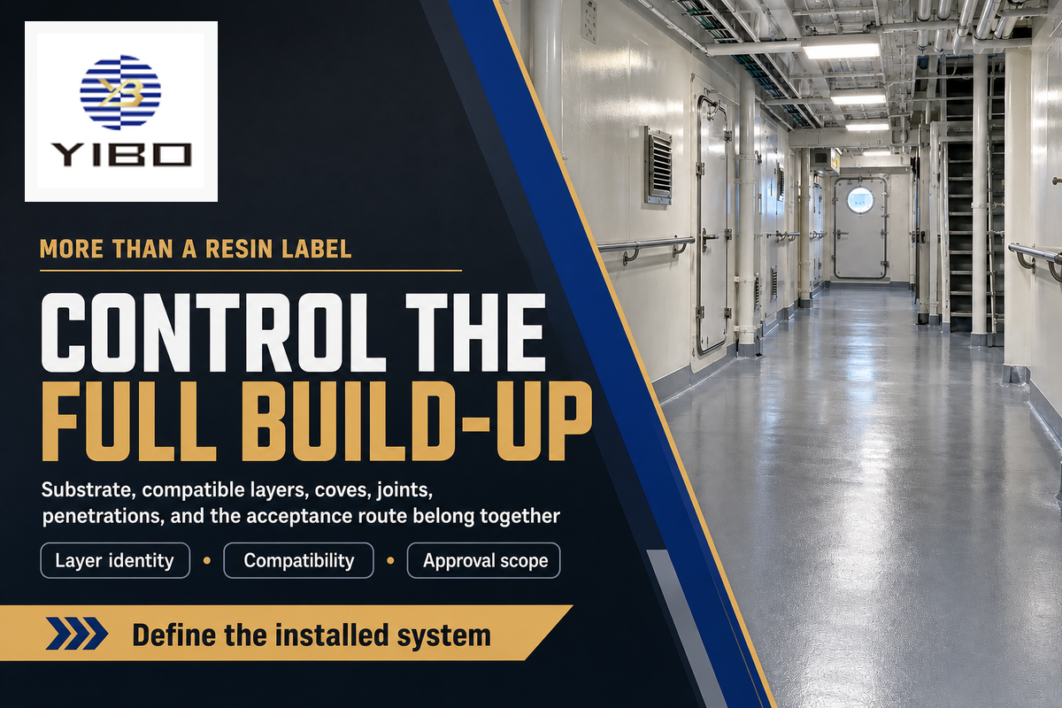
A marine epoxy floor is an installed build-up, not a bucket of resin. Depending on the vessel and available space, that build-up may include prepared deck plating, corrosion protection, primer, one or more resin layers, aggregate, and a topcoat, along with coves, joints, and detailing around penetrations. The finish name is important, but so is the compatibility of the various elements in the build-up.
Classification also follows the installed layer. The U.S. Coast Guard finish and furnishing guidance distinguishes a primary deck covering applied at deck level from a floor finish above it and from paint or interior-finish categories. That distinction doesn’t decide the route for every flag or vessel, but it shows why a commercial phrase can’t replace a layer drawing and an approval review.
The same phrase is also used for leisure-boat repair resin, plywood sealing, garage coatings and retail laminating kits. These materials may have their uses in certain applications; however, the search labels for these materials don’t address their use in an occupied ship space, a working deck or a specified marine floor assembly.
In marine environments, a high performance floor requires the ability to withstand the documented traffic, liquids, cleaning and climate. This doesn’t mean that all epoxy resins are interchangeable. Epoxy systems also differ in flexibility, UV resistance, primer requirements, fillers and topcoat compatibility, so the installed assembly matters more than a broad chemistry label.
Teams that have specified the vessel, space and floor build-up can review Yibo’s marine epoxy floor solution page for product-specific discussion. This guide covers the educational work: planning, installation evidence, inspection, troubleshooting and repair decisions.
Start With Service Conditions and Substrate Evidence
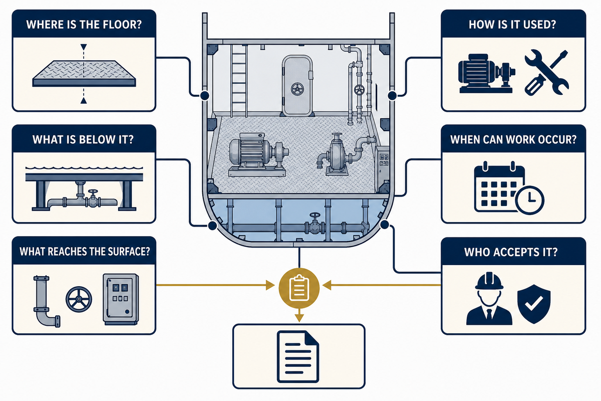
A reliable installation brief describes the function of the floor and evidence for its release. “Engine Room,” “Galley” or “Accommodation” are preliminary designations. The team still needs to identify the liquids, traffic, cleaning, footwear, heat, drainage, movement, access window and acceptance route in that zone. The US Coast Guard finish and furnishing guidance illustrates why the product category and approved arrangement must remain part of that decision.
Instead of using “marine grade” as a placeholder for missing details, use an open issue list. Each item should have an owner and a definitive time by which it needs to be resolved. It may change the preparation method, the order of layers, their texture, the planned inspection and the protection of the cure.
| Question | Evidence to collect | Why it changes the plan | Escalate when |
|---|---|---|---|
| Where is the floor? | Vessel, deck, space, boundaries and adjacent trades | Defines the operating and approval context | The space or layer classification is unclear |
| What is below it? | Substrate type, existing layers, repairs, corrosion and movement details | Changes preparation, primer and test suitability | Existing layers or contamination cannot be identified |
| What reaches the surface? | Water, oils, chemicals, heat, ultraviolet exposure and cleaning agents | Affects resin, topcoat, detailing and maintenance | Exposure concentration, temperature or duration is unknown |
| How is it used? | People, carts, dropped tools, footwear, wet traffic and cleaning method | Drives texture, wear and repair priorities | The proposed finish has no service-relevant validation |
| When can work occur? | Access, ventilation, temperature, humidity, neighboring work and return-to-service date | Determines work-front size and cure protection | The schedule requires release before documented cure conditions |
| Who accepts it? | Drawing, specification, method, inspection plan and responsible parties | Turns observations into auditable decisions | Documents conflict or no one owns the release |
Treat slip resistance as a use condition
A general non-skid description doesn’t answer how a surface behaves with the project’s contaminants, footwear, and cleaning practices. Define if the surface is normally dry, frequently wet, or exposed to oil and other contaminants. Include slopes, drains, turning points, and direction of travel. Then identify the specified test method and acceptance criteria, if any.
Texture doesn’t depend on a single element; it must be evaluated with the full floor system. A rougher finish may result in poor cleanability, increased liquid retention and loss of film continuity and may show increased wear. These interactions must be validated for the given system and can’t be reduced to a universal aggregate value or a standalone reason for selection.
Surface Preparation Is the First Release Decision
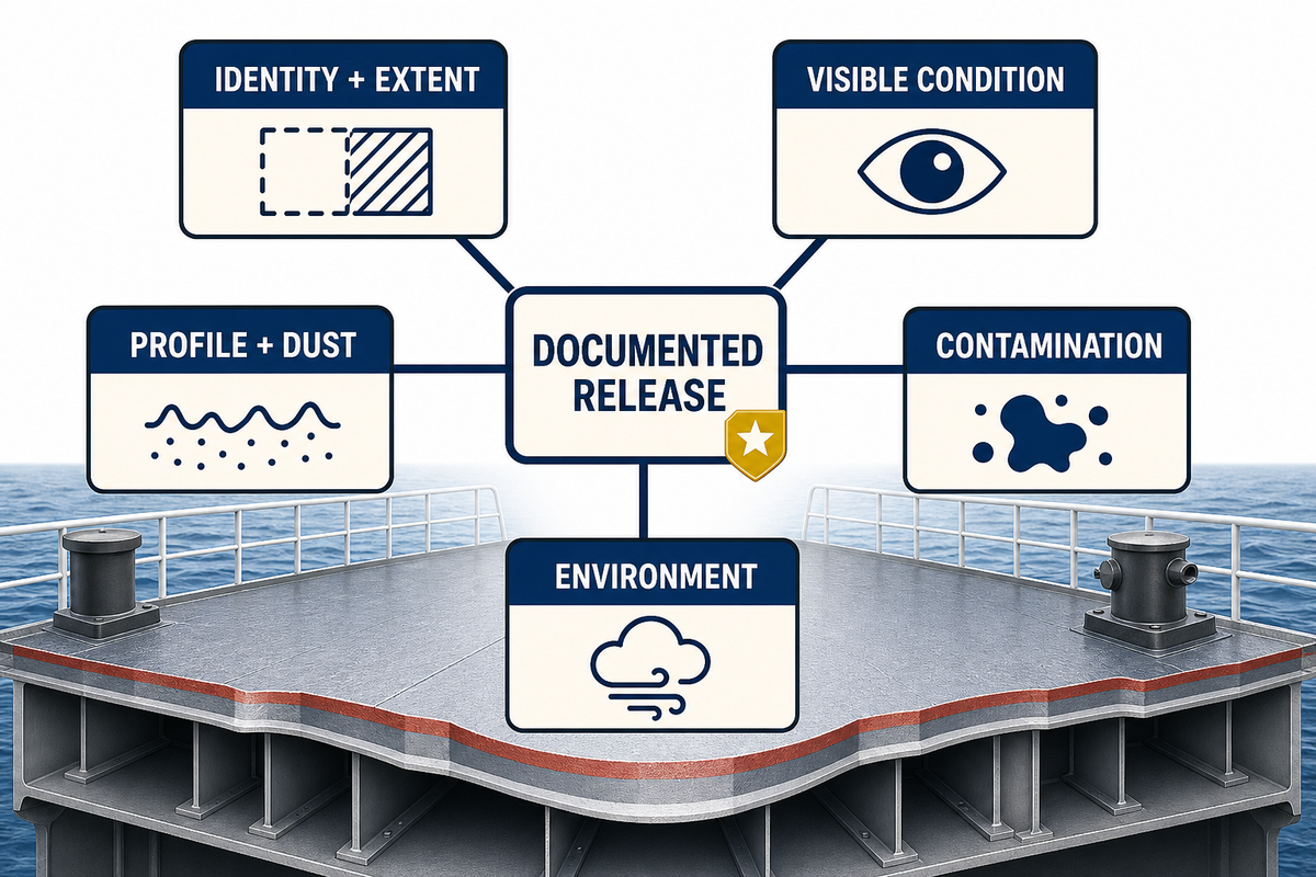
Surface preparation is complete when all the references are checked and documented, not when the surface appears to be clean and bright. A surface profile, dust, soluble contamination and the likelihood of condensation answer a different question each. One acceptable report can’t replace the other answers.
Depending on whether the surface being treated is steel, aluminum, cementitious underlay, coating or a mixed repair area, the required method may differ. Edges, drains, penetrations, welds and pits as well as transitions require close scrutiny and inspection, as a broad deck review may fail to identify a local path of loss of continuity. The selected system will also determine whether a primer or tie coat will be required or if application may be done directly.
The Intershield 852 guide defines the boundaries of its own named application method; it isn’t a general marine-deck specification. It describes preparation and shows why the method must be documented: its rules are valid for the Intershield 852 system, aren’t general guidelines and can’t be copied to other products.
| Evidence domain | Record | Decision question |
|---|---|---|
| Identity and extent | Area map, substrate, existing layers and repair limits | Are all surfaces inside the method’s scope? |
| Visible condition | Corrosion, welds, edges, defects, cracks, pits and residues | Are repairs complete before coating begins? |
| Profile and dust | Method, instrument or comparator, locations and results | Does the prepared surface match the referenced method? |
| Contamination | Oil, grease, soluble contamination and cleaning closure | Could a non-visible residue undermine adhesion? |
| Environment | Air and surface conditions, humidity, condensation risk, time and location | Can the surface remain within the specified application limits? |
| Release | Inspector, referenced limit, result, deviation and disposition | Is mixing permitted for this work front? |
Control Mixing, Work Fronts, Film Build and Cure
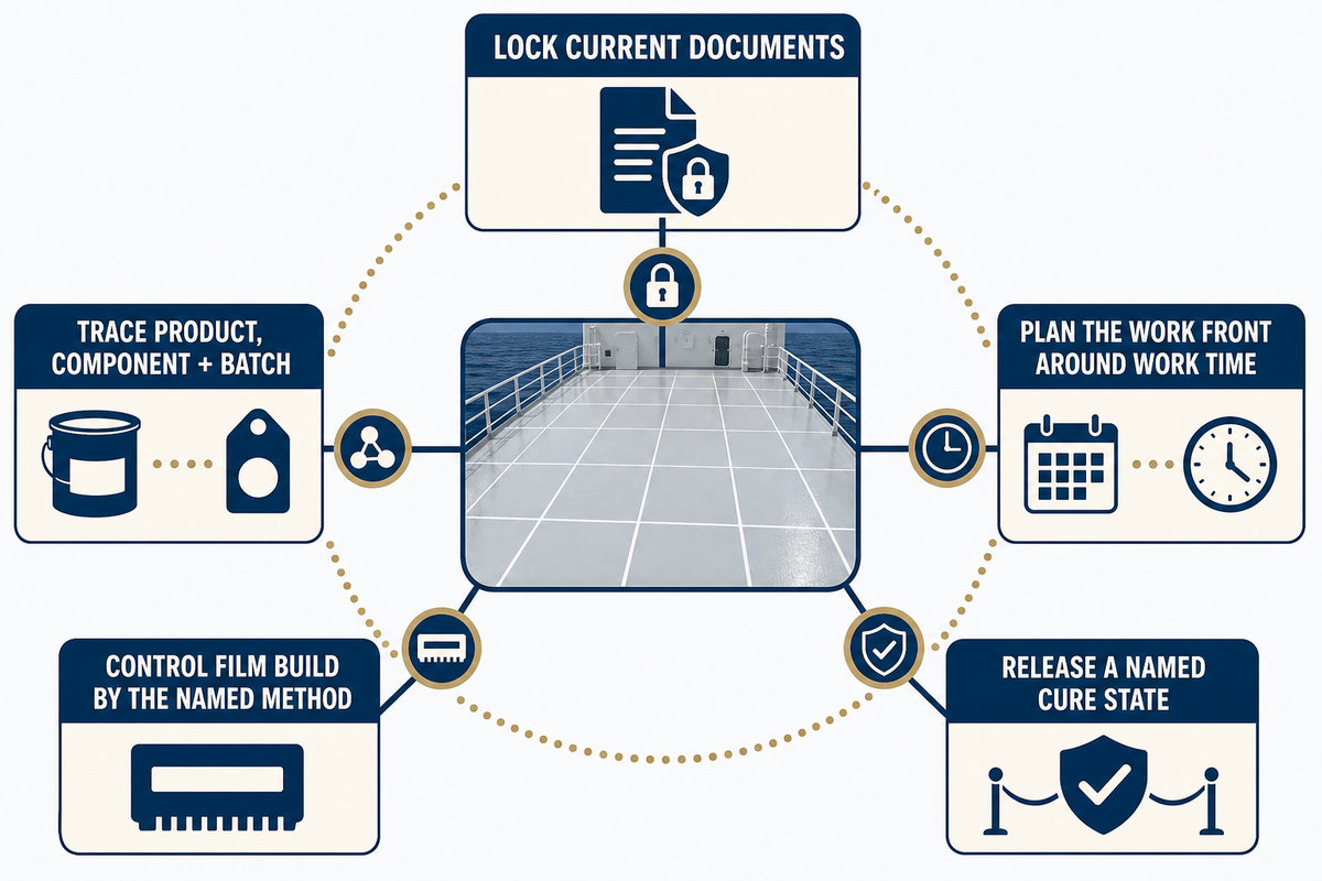
Lock the technical data sheet, safety data sheet and approved build-up and project method while materials are sealed. Record the manufacturer, product, component, batch, shelf life status and storage conditions at the mixing station. Pre-measuring a component to split without an approved measuring method creates a ratio risk that the finished appearance may not reveal.
Organize the work front around the documented work time and the crew’s known placement rate. Consider time and equipment for mixing, transfer, spreading, detailing and finishing. A large mixed batch is inefficient if its last portion must be placed after the permitted time for work. A small work front is uncontrolled if its edges and sequencing and tie-in times are undefined.
Each system requires an appropriate method for film build. In the case of a liquid film with a smooth surface, direct wet film checks can work. For a heavily textured or aggregate-filled surface, material-volume, area, or other project controls may be needed. For example, the AkzoNobel guide warns against overapplication within its named system and provides product-specific coverage and cure information. This is evidence against the shortcut that “more material is safer.”
The table following makes the document control point visible. Each value comes from a single 2016 Intershield 852 application guide and only applies under the conditions stated in that guide. It’s neither a Yibo nor an average industry specification nor a substitute for the currently issued documents.
| Published condition | Published time | Decision use |
|---|---|---|
| Pot life at 10°C | 8.0 hours | Bind the temperature to the time record |
| Pot life at 15°C | 7.0 hours | Keep the source curve with the batch plan |
| Pot life at 20°C | 6.5 hours | Show why one time cannot cover every condition |
| Pot life at 25°C | 6.0 hours | Check the planned work front against the named curve |
| Pot life at 30°C | 5.0 hours | Record the condition actually used |
| Pot life at 35°C | 4.0 hours | Connect placement planning to temperature |
| Pot life at 40°C | 3.5 hours | Prevent use of a colder-condition value |
| Touch dry at 10°C | 12.0 hours | Keep touch dry separate from other release states |
| Control type | Published example | How this guide uses it |
|---|---|---|
| Vertical preparation extent | 50 mm to 75 mm | Shows that boundaries may extend beyond the flat deck |
| Minimum profile example | 75 μm | Must stay with the named steel-preparation method |
| Dry-film example | 200 μm | Illustrates product-specific volume-area control |
| Coverage example | 2.62 m² per litre | Paired with that document’s dry-film example |
| Cure-graph film basis | 400 μm | Shows why cure data cannot be separated from build |
| Preferred cure temperature | Above 10°C | A named-system condition, not a universal threshold |
| Prolonged storage warning | Above 25°C or 77°F | Connects material condition to storage history |
| Winter trigger example | Below 10°C or 50°F | Demonstrates seasonal handling instructions |
| Winter preconditioning | Above 10°C or 50°F for at least 48 hours | Shows why storage belongs in the batch record |
| Chloride example | 0.0025% by weight | Remains tied to the cited guide and method |
| Profile range example | 75 μm to 112 μm | Shows that instrument and method matter |
| Needle-gauge example | 75 μm | Cannot be copied without the associated technique |
| Nozzle example | 6 mm to 10 mm | Equipment values belong to the named application method |
| Air-pressure example | At least 80 psi | Not a floor-category requirement |
| Roller-overlap example | About 7.5 cm | Technique remains system and tool specific |
| Spray distance example | 50 cm to 60 cm | Connects equipment setup to application control |
| Spray-cone example | About 15 cm | Useful only with the cited equipment method |
| Application-rate example | 3 m² to 4 m² per minute | Shows why work-front planning needs the exact document |
Do
- Trace each mixed unit to a batch and work area.
- Record mix start, placement finish and environmental readings.
- Use the current product method for build, recoat and cure.
- Stop when a component, ratio or work-time record is uncertain.
Don’t
- Add hardener to force a faster cure.
- Add thinner unless the current method expressly permits it.
- Blend expired material into a fresh work front.
- Treat surface hardness as proof of full-service readiness.
Protect the people and the work front
Safety controls in the shipyard must not be superseded by quality controls. The work pack should address current safety data sheets, appropriate ventilation and protective equipment, ignition controls, nearby activities, provision for spill and waste control, and, where applicable, any permits and confined space entries. The individual releasing the work front should know which safety conditions may require mixing or application to stop.
Name the cure state you are releasing
“Cured” is an ambiguous term. Tack-free, ready for another coat, ready for foot traffic and ready for intended service may occur at different times. Record the actual conditions and the specific release being granted. If the surface is soft, tacky, contaminated or outside its documented recoat window, stop and obtain a disposition before covering it.
Build a Mixed-Unit-to-Workfront Trace Chain
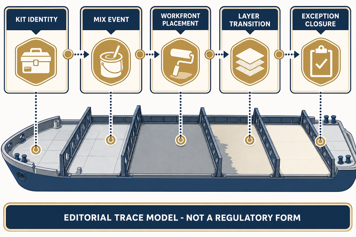
Two-component floor work can look continuous even when its records are fragmented. The following editorial trace chain connects each unopened kit to one mix event, a mapped workfront, a stated layer transition and any later exception. It is neither a class-society form nor a regulatory checklist. For an authority example of documented coating work, inspection and quality-control responsibilities, consult the current NAVSEA Standard Item 009-32; the project specification still controls the actual floor work.
| Trace link | Record owner | Evidence to connect | Broken-link signal | Decision enabled |
|---|---|---|---|---|
| Kit identity | Material controller | Product, component and batch identity; shelf-life status; storage release | A component or its status cannot be matched to the work pack | Release the complete kit to the mix station |
| Mix event | Mixing operator or supervisor | Component quantities, mix start, method, material temperature and mixed-unit identifier | Ratio, time, identity or method is uncertain | Assign that mixed unit to a defined workfront |
| Workfront placement | Application supervisor | Mapped start and finish boundaries, placement times, environment and build checks | The affected area cannot be isolated if a batch question arises | Protect and inspect the traceable area |
| Layer transition | Responsible inspector | Actual conditions, elapsed time, surface condition and the named recoat, traffic or service state | The next activity is requested without its release state | Authorize only the stated next layer or activity |
| Exception closure | Project technical authority | Affected mixed unit and area, defect evidence, disposition, repair record and reinspection | A defect or deviation cannot be traced back to defined material and boundaries | Close the exception without losing batch-to-area history |
A trace link is useful only when it narrows the affected material and area. “Monitor” isn’t a disposition unless the record states who will monitor, what will be measured, when the review will occur and which result will stop work. Document the exception, its mapped boundaries and the authority that approved it.
Inspect Before the Next Coat or Trade

An inspection should answer three distinct questions: what was observed, which requirement is applicable, and what decision results. A glossy, level or hard-looking floor may still have an unresolved bond, cure, contamination or recoat question. However, a superficial variation may be acceptable if it doesn’t contravene the documented requirement. The record should preserve that distinction.
Start by drawing an area map. Link every batch, every mixing period, every environmental reading, every build observation, every defect, and every repair to the map. If a result only concerns one location, don’t let the report imply that it concerns the entire compartment. Sampling plan and acceptance criteria should be included in the inspection plan.
When pull-off adhesion testing is specified and suitable for the actual substrate, record more than the result; the project-specified primary method remains the authority for procedure and acceptance. The article on the Elcometer method provides a practical overview of bonding a dolly and applying force perpendicular to the surface. The article also describes the importance of the type of failure and the adhesive used in the test. The report should define the specified method, instrument, dolly location, result, failure plane, repair of the destructive test location and acceptance source. The project specification, not this secondary article, should define the method and acceptance limit.
| Record group | Minimum useful content | Closure test |
|---|---|---|
| Area and layer | Mapped boundary, substrate and installed layer | Matches the drawing and work pack |
| Material | Product, component, batch and storage/shelf-life status | Traceable to the material record |
| Application | Mix and placement times, work front, crew and build method | Inside the documented method |
| Environment | Location, time, readings, instrument and specified limit | Supports the claimed application and cure state |
| Inspection and tests | Observation or method, sample location, result and acceptance source | Every result has a disposition |
| Defects and repairs | Photograph, map, cause review, repair method and reinspection | No open repair or erased evidence |
| Release | Area, permitted next activity, exceptions, date and authority | The recipient knows exactly what is accepted |
Continue the record after handover
The records of maintenance should indicate the cleaning chemicals involved and method, abrasion zones, damages at drains, edges and joints, chemical incidents, repairs and the repeat locations. Recurrences are significant. Repeated failure at one transition may indicate movement or detailing; widespread loss after one batch may indicate application or cure; localized impact damage may support a local repair. Set the inspection interval based on service conditions and the project objective rather than establishing one universal interval.
Diagnose Blisters, Pinholes, Delamination, Soft Cure and Cracking
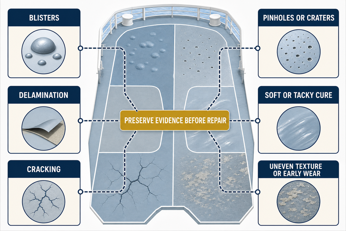
A defect name serves only to identify its appearance. It doesn’t establish a cause. Prior to grinding, cutting or solvent cleaning, map the extent, photograph the surface and edges, indicate the affected layer, preserve useful loose material, and retain the batch, mixing, environmental, build, cure and traffic records for that work front.
The 2020 edition (no older editions are claimed) of the Dex-O-Tex problem-solving guide and an undated Sherwin-Williams troubleshooting article are general references for issues regarding resin flooring. They describe possible cause families for symptoms such as bubbles, delamination and poor cure, but they aren’t current marine specifications or evidence that any cause exists on a particular vessel. The matrix below uses them only to retain the hypotheses for the investigation. Repair instructions and acceptance criteria must come from the current project documents, the selected system supplier and the responsible technical authority.
| Symptom | Collect before disturbance | Possible cause families | Immediate containment | Proof before return |
|---|---|---|---|---|
| Blisters | Size, distribution, layer, fluid or gas, substrate and exposure history | Moisture, osmotic pressure, trapped solvent or air, contamination, weak intercoat bond | Protect the area and stop covering adjacent suspect zones | Cause review, sound boundary, compatible rebuild and reinspection |
| Pinholes or craters | Density, depth, work sequence, mixing, rolling, temperature trend and substrate porosity | Outgassing, air entrainment, unsuitable conditions, excessive build or late working | Keep liquids and contamination out of the area | Continuity restored by the approved method and verified |
| Delamination | Failure plane, perimeter soundness, preparation, contamination and recoat records | Weak substrate, inadequate preparation, moisture, contamination, primer or intercoat incompatibility | Remove loading and map the suspect boundary | Removal to sound material, restored preparation, bond evidence and closed edges |
| Soft or tacky cure | Components, ratio, batch, mix station, temperatures, time and affected pattern | Missing component, wrong ratio, incomplete mixing, cold material or incompatible contamination | Stop traffic and do not hide it with another coat | Uncured material removed or technically accepted; rebuild reaches the stated release |
| Cracking | Crack width/pattern, substrate movement, joints, thickness transition and loading history | Substrate movement, restrained shrinkage, impact, thermal movement or rigid bridging | Mark ends and monitor active movement where directed | Movement source addressed and detail rebuilt to an approved design |
| Uneven texture or early wear | Traffic map, aggregate distribution, build, cleaning and service exposure | Application variation, wrong work timing, insufficient build, unsuitable service or aggressive cleaning | Control access and separate cosmetic from safety-critical areas | Required texture and continuity restored under the project method |
Cause families may overlap. A blister may be caused by moisture, for example, but the path might be an edge, a pinhole, a crack, a contaminated interface or even the substrate itself. A tacky patch may be a local mixing miss or may be an indication that a larger batch was affected. The investigation should test the various competing explanations before a repair is conducted to ensure the evidence isn’t destroyed.
Repair or Replace? Use a Scope-of-Failure Decision
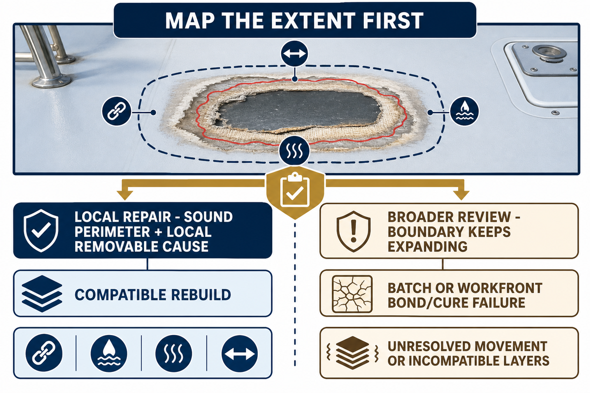
A local repair can be acceptable if the defect is bounded and if the surrounding material is in sound condition, if the cause is known, if uncured resin or contamination can be removed, and if the approved system offers a compatible rebuild. A broad repair may be required when there’s bond loss, contamination, incorrect ratio, missed cure or substrate movement that extends beyond the observed symptom. Neither of these options should be selected based solely on appearance.
Local repair may be defensible when
- The extent is mapped and stable.
- The perimeter is demonstrably sound.
- The failure cause is local and removable.
- The rebuild is compatible with the existing layers.
- The repair purpose and service limit are documented.
Broader technical review is needed when
- The suspect boundary keeps expanding.
- Bond or cure failure appears across a batch or work front.
- Contamination extends into the substrate or between layers.
- Movement or incompatible layers remain unresolved.
- Approval scope or permanent service would be changed.
Two fields that are usually omitted are purpose of repair and life of repair. An approved temporary localized repair that protects the damaged area until drydock has a different decision basis from a permanent repair that returns the system to full service. The handover must specify which decision has been accepted and what follow-up is required.
Prior to requesting a project-specific review, provide the vessel and space, the substrate and overlying layers, the mapped area and adjacent transitions, the exposure and anticipated traffic, cleaning and slip requirements, the intended surface, the planned duration of the work, constraints in the environment, the acceptance process and supporting documents. This information can enable a technical decision to be made without providing specific product requirements and without a quotation.
Key takeaway
Release the evidence, not the appearance: every layer, batch, work front, cure state, defect and repair should be tied to a named decision before the next activity begins.
Turn the field record into a project review
Bring the vessel space, substrate, exposure, floor build up, acceptance route, schedule and inspection criteria. Yibo may use this information in discussing the project-specific system and supporting documents. For adjacent planning routes, review Yibo’s resin floor system family, flooring applications by vessel area, marine deck covering system family and primary deck covering field guide.
Marine Epoxy Floor FAQ
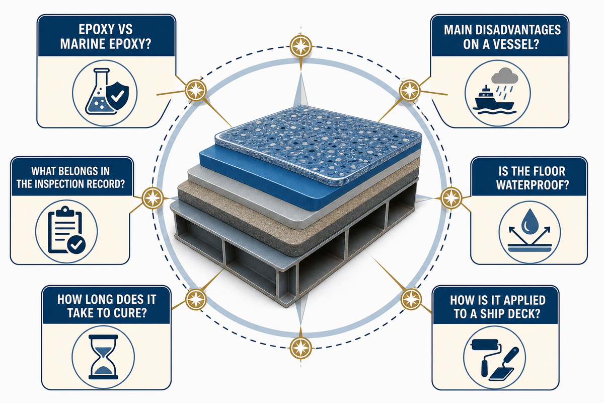
Is there a difference between epoxy and marine epoxy?
“Marine epoxy” is a use-case label; it doesn’t define one universal formula or approval status. Resin-based flooring systems may vary in chemistry, fillers, flexibility, layer build-up, curing behavior, surface texture and compatibility with primers and substrates. Retail marine resin may not be intended for use as a finished component of a ship floor.
An installed floor may also require a primer, aggregate, topcoat, coves and details that aren’t included in a resin kit. Instead of considering two labels as complete specifications, evaluate the completely documented system for the real vessel space, substrate, exposure, and the route for acceptance. The US Coast Guard category guidance is one example of why the installed arrangement and approval route matter. If the product description fails to disclose the tested or approved arrangement, demand the latest supporting documents before the selection is made.
What are the main disadvantages of epoxy flooring on a vessel?
Potential problems may include sensitivity to poor preparation, moisture, or contamination; incorrect ratio of components, missed recoats, inadequate cure conditions, exposure to UV, movement of the substrate, and a texture that’s unsuitable for wet traffic or cleaning. The respective disadvantages depend on the selected system and the service conditions, with risks linked in the record to defined inspection points and named responsible disposition owners. Therefore, each applicable risk should be converted to a control and inspection record by the project.
Is a marine epoxy floor waterproof?
A suitable, continuous and fully cured resin layer may provide a low-permeability barrier, but “waterproof” isn’t an unconditional system result. Pinholes, cracks, edges, penetrations, damaged areas, poor adhesion and incompatible layers can create pathways, which makes continuous detailing and inspection part of the acceptance decision.
Before relying on the layer for water resistance, confirm the build-up, detailing, exposure, and inspection criteria.
How do you apply marine-grade epoxy to a ship deck?
Begin with the approved work pack. Identify the layer and substrate, complete repairs, prepare and release the deck, confirm environmental conditions, trace and mix the components, control the work front and film build, protect the cure, inspect the finished area and close defects prior to the next coat, trade or service. Exact preparation grades, ratios, times and thicknesses are provided in the project and product documents, with the work record showing release authority, stage, and controlling document used for approval.
How long does a marine epoxy floor take to cure?
There’s no universal safe time. Curing is a function of product chemistry, layer build, material and surface temperature, humidity, ventilation and the requested release. Tack-free, recoat-ready, walk-on and full-service conditions may differ, which means the named release state needs to match the recorded conditions.
Record the actual conditions and either use the project approved technical advice or the current product cure table.
What belongs in a marine epoxy floor inspection record?
Record the area, layer, and substrate, preparation, the presence of contamination and the environment, product and batch ID, the time for mixing and placement, the checks on the build, the decision for cure or recoat and the specified test method and its result, along with the defects, the repairs, exceptions and the final release.
Every measurement must identify its location, instrument, acceptance source and disposition.
References & Sources
- U.S. Coast Guard, Finish & Furnishing Materials (category and approval-scope guidance)
- NAVSEA Standard Item 009-32, FY24 (scoped U.S. Navy marine-coating process reference)
- AkzoNobel Intershield 852 Exterior Deck System Application Guidelines (product-specific marine-deck example)
- Elcometer, Pull-Off Adhesion Testing Technique (test-method and interpretation context)
- Dex-O-Tex Epoxy Floor Coating Problem Solving Guide (general defect cause families)
- Sherwin-Williams, Why Is My Epoxy Floor Bubbly or Gummy? (resin-floor troubleshooting context)
- U.S. Bureau of Reclamation, Guide to Protective Coatings Inspection and Maintenance (inspection background)
Author: DD
Commercial marine flooring systems
Plan the deck build-up before the workfront is released.
Yibo manufactures commercial marine flooring systems in Suzhou for vessel projects that need a coordinated deck-covering, resin-floor, or acoustic-floating-floor build-up.
Review marine deck covering systems, marine resin floor systems, and marine acoustic floor systems against the vessel area and planned application sequence.
Project enquiry
Give the engineering team the inputs that shape the system review.
Include the vessel area, substrate or deck condition, intended floor build-up, fire or acoustic target, and project schedule so the enquiry can begin with the relevant deck constraints.
Send Your Deck Schedule


![Marine PU Floor: Selection & Installation [Guide]](https://yibomarine.com/wp-content/uploads/2026/09/marine-pu-floor-blog-featured-150x150.png)