Get in touch with Yibo Company


Primary Deck Covering: Types, Installation, Inspection & Selection Guide


Updated September 2026 · Author: DD
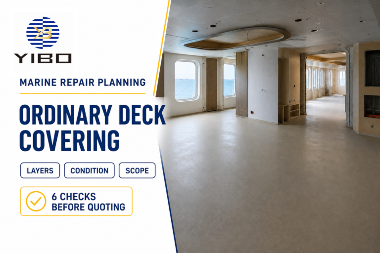
Primary deck covering is the base layer of a ship’s floor build-up, installed in direct contact with the deck plating. Depending on the applicable system, that definition can also encompass a primer, anticorrosive compound, or adhesive used for protection or bonding. This layer creates a suitable base for the level flooring system that will be installed on top of it. This layer isn’t the finished floor surface, an acoustical floating floor or a complete fire-rated assembly.
The short answer
Control five release decisions: the project brief, substrate, material batch and placement, cure conditions, and final handover. Take the exact primer, mixing method, thickness, cure criteria, and tests from the product instructions, approved construction, and responsible project authority.
This distinction is necessary because the phrase “deck covering” is easy to confuse with a decorative deck surface. This guide is for shipyard engineers, flooring contractors, owner representatives, quality teams, and buyers preparing a marine floor build-up. This guide documents the decisions and records that should exist before a model is selected. This doesn’t replace a current product data sheet, approved installation procedures, flag and class requirements, or a vessel-specific technical review.
What Primary Deck Covering Is, and Is Not

The United States Coast Guard’s finish and furnishing guidance places primary deck covering at the bottom of the floor construction, directly on the deck plating. That definition can include any primer, anticorrosive compound, or adhesive needed to protect the deck or secure the covering. Anything above that layer is considered floor covering.
“The first layer of floor construction which is applied directly on top of the deck plating.”
The first step is a layer drawing, not a product name. Draw the structural plate, corrosion protection or adhesion layer, the primary cover, and the finish or assembly that will be placed on top. If a waterproof membrane, acoustic layer, insulation, decorative surface, or a fire barrier is provided, include it in the drawing. This is helpful to avoid using the same word to describe different materials for design, purchasing, and installation.
| Layer question | What to identify | Common mix-up |
|---|---|---|
| Structural base | Steel, aluminium or another specified deck substrate and its condition | Treating all prepared metal surfaces as interchangeable |
| Protection and adhesion | Qualified primer, bond coat, anticorrosive layer or adhesive, when applicable | Assuming every system always needs a separate primer |
| Primary covering | The underlay or fairing layer, including its permitted thickness and use | Calling it the exposed decorative floor |
| Layers above | Finish, membrane, insulation, acoustic construction or another approved layer | Assigning a complete assembly rating to one generic material name |
The standards boundary
The public abstract for ISO 5694:2023 covers deck-covering underlay of the cementitious type and excludes overlay floor coverings such as tile, carpet and rubber sheet. That scope is useful, but it does not turn ISO 5694 into a rule for every polyurethane, cork-composite, exposed or multi-layer system.
Current US approval language also needs a jurisdiction label. 46 CFR Subpart 164.106 cites the 2010 Fire Test Procedures Code Annex 1, Part 5 and Part 2 for the US Coast Guard approved route. An older Coast Guard explanatory page still mentions legacy Part 6 language, so the current regulation controls that detail. For another flag, administration, or project, verify the approved route that applies rather than using the US section language.
Key takeaway
A product name, certificate reference or fire-test label does not by itself prove every substrate, primer, adhesive, thickness and final floor build-up. Verify the tested and approved scope that matches the project.
How Functional Types Change the Installation Method
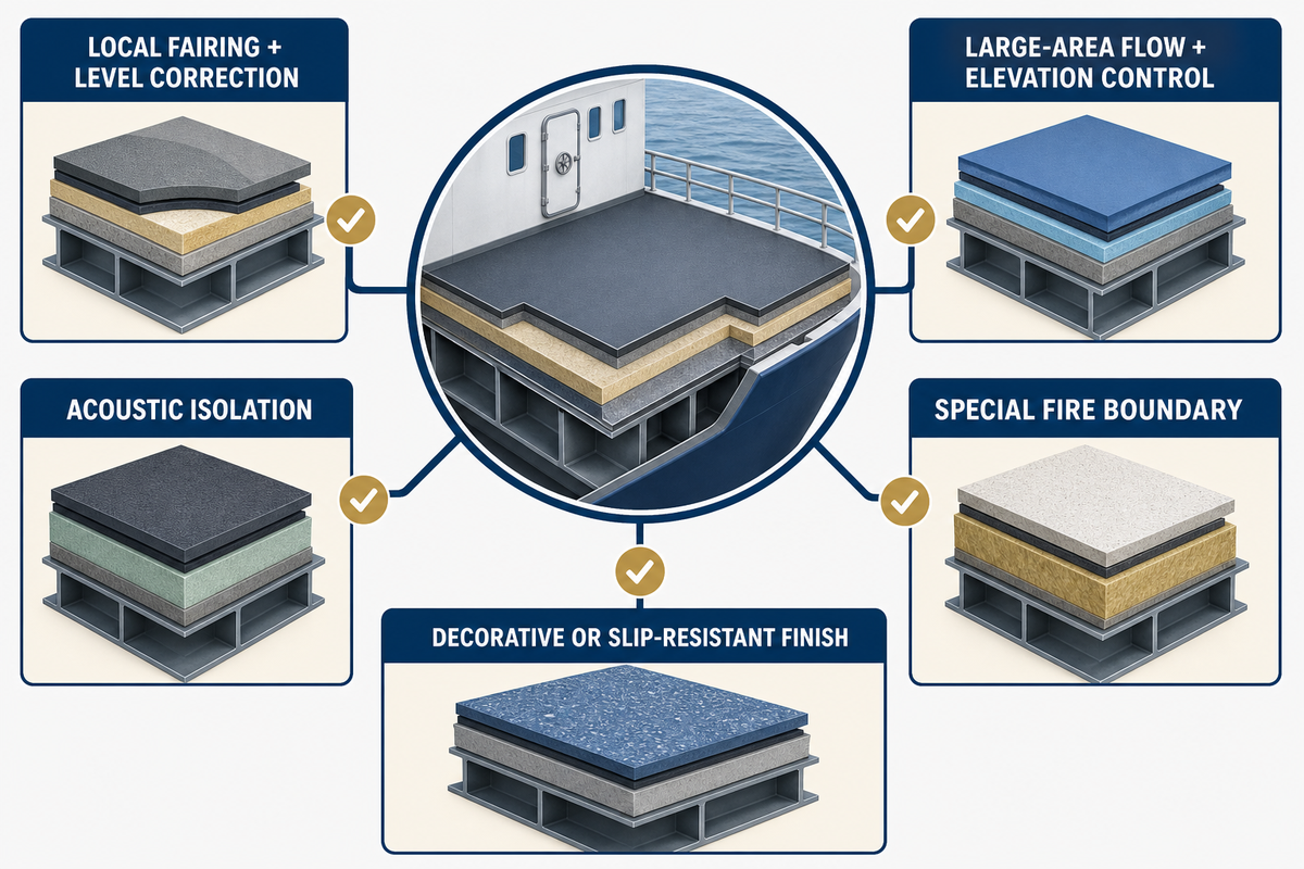
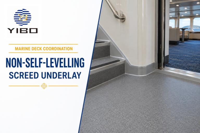
Categorize what the function is and how it will be installed when evaluating several options. Terms such as “primary,” “self-leveling,” “screed,” “underlayment,” and “floating floor” identify different functions within the overall build-up. One option may meet more than one of these descriptions, but the terms aren’t interchangeable.
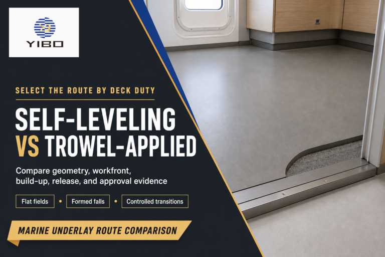
Trowelled material offers control over edges, penetrations and local falls with the potential for variability related to mixing, workability and finishing. A pumpable or self-leveling material may allow a larger work front and flow into a datum-controlled area, but edges, openings, drains and transitions still require physical control. Lower-density material may support the weight budget, but assess density together with thickness, strength, substrate, finish, and approval scope.
| Project need | System family to investigate | Question that prevents a false match |
|---|---|---|
| Local fairing and level correction | Trowelled underlay or approved patch/fairing material | What are the permitted edge, layer and substrate conditions? |
| Large-area flow and elevation control | Pumpable or self-leveling primary covering | How are work-front size, stops, datum and thickness controlled? |
| Acoustic isolation | Multi-component floating-floor construction | Which assembly, interfaces and test scope carry the acoustic duty? |
| Special fire boundary | Tested construction with named layers | Does the proposed full build-up match the approved construction? |
| Decorative or slip-resistant exposed finish | Finish flooring or exposed deck system | Is an underlay still needed, and who owns surface acceptance? |
The material chemistry impacts the placement as well as the methodology. Water instructions are chemistry-specific: a cementitious mix may call for a measured addition, whereas a two-component polyurethane underlayment may forbid extra water. Because of this disparity, a ‘deck screed recipe’ shouldn’t be considered generic. The current project methodology and product description should be fixed before scheduling the work.
A terminology scope filter
Use this filter when a search term appears in a drawing or request. These terms describe adjacent layers, vessel settings or evidence questions; they do not select a product by themselves.
| Term group | What the project must clarify |
|---|---|
| Cabin, interior and interior decks | The occupied space, finish and interior acceptance route. |
| Cruise ships, passenger vessels, ferry or passenger setting | Traffic, accommodation use and the responsible approval authority. |
| Naval, offshore or navigation spaces | The vessel-specific specification and service exposure. |
| Exterior, outdoor, dock or helicopter deck setting | Weathering and non-slip duties that may sit outside an interior primary-covering brief. |
| Synthetic teak, teak decking, vinyl or PVC finish | The overlay, adhesive and finish-ready interface above the primary layer. |
| Epoxy, resin, polymer or one-component system | Product chemistry, mixing rule, layer limit and compatible substrate. |
| Thermal duty, thermal insulation, damp deck or stability property | The measured requirement and the tested construction that addresses it. |
| 2010 FTP Code, FTP Code, MSC or EU route | The exact jurisdiction, document revision and approved construction; the terms are not interchangeable approvals. |
| Supplier claims to certify durable, non-slip or sustainability performance | The test method, certificate owner, scope and current supporting record. |
| Marine flooring, marine primary deck covering or a specific deck | The layer location, target function, final finish and acceptance boundary. |
The Project Brief Before Product Selection

A proper recommendation will consider the vessel space and layer stack prior to considering the price or bag size. Use one brief sheet to record the space and drawing reference, substrate, present condition, area, target elevations, final finish, exposure, traffic, acceptance route, work window, and governing document language. Each agreed-upon document revision should be used by engineering, purchasing, installation and quality control.
The space title should describe the area; it shouldn’t replace the project specification. The areas may suggest functional differences related to cleaning, draining, heat or contamination, but they don’t dictate a product. The actual specification and authority path determine the applicable requirements.
A manufacturer-published river-yacht case outlines four vessels, approximately 2,000 m² of deck area, approximately 900 m² of supplied material, 3D laser mapping, and prefabrication. The lesson isn’t a promise of a transferable performance. The lesson is that material planning, geometry, zone breakdown, and installation sequence belong in the brief.
Minimum one-page brief
- Vessel, space, drawing revision and responsible parties
- Substrate material, condition, preparation route and any retained coating
- Target elevation, falls, edges, penetrations and transitions
- Final floor, membrane, insulation or acoustic layers above
- Fire, flag, class, owner and inspection-plan requirements
- Work area, access, ambient constraints, following trade date, and required documents.
The complete brief reduces model-shopping noise. It does not replace the current technical sheet or technical data. A rush date doesn’t displace the defined cure or release criteria. If the next trade’s date is fixed, work backwards from finish-ready release rather than taking “surface feels hard” as acceptance criteria.
Substrate Readiness Before Mixing
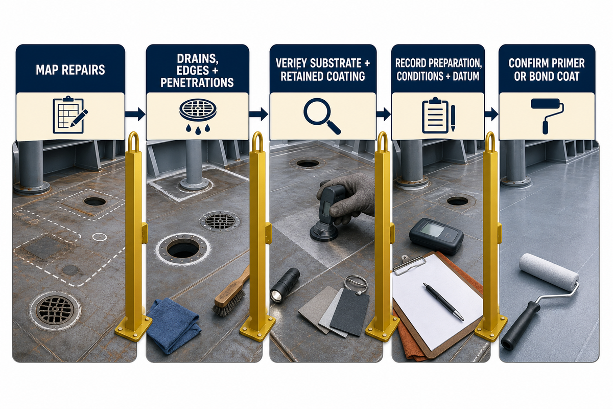
Make substrate release a true hold point. Before opening material, verify the area, preparation method, repairs, penetrations, drains, joints, edge details, datum points, ambient conditions, and the selected primer or bond-coat requirement. Even a clean-looking surface can retain oil, soluble contamination, loose corrosion, unsupported repairs, and an incompatible retained coating.
The example of the official NAVSEA Standard Item 009-26 is helpful. For an invoked US Navy work item, it calls for an inspection of the exposed plating, drains and penetrations for deterioration, pitting, cracks, damage and distortion. It also instructs the solvent cleaned surfaces to be dried before the succeeding step. While not generalized commercial-vessel acceptance criteria, they demonstrate what a substrate release can show.
The same document shows that a shortcut of “always prime” isn’t acceptable. Some qualified systems employ a primer or bond coat, while specified MIL-PRF-3135 Types III and IV use a direct-to-substrate preparation without primer. Therefore, zinc-rich coatings, galvanized steel, and aluminum along with other primers should be addressed on the approval and compatibility list. In every case, follow the procedure written for the selected system.
Do
- Map repairs, drains, edges and penetrations.
- Verify the named substrate and retained coating.
- Record preparation, conditions and datum release.
- Confirm the system-specific primer or bond coat.
Don’t
- Release an area from appearance alone.
- Transfer a steel instruction to aluminium.
- Hide unresolved corrosion beneath the underlay.
- Open material before the work front is ready.
What the substrate-release record should contain
Record the drawing and area boundary, substrate, preparation status, closed repairs, primer or bond coat (if applicable), batch (if applicable), temperature and surface condition, accepted elevations, photographs or inspection references, and the person and time releasing the work front. The record is an editorial control framework, not a claim that every project authority mandates these exact fields.
Mixing, Placement and Thickness Control
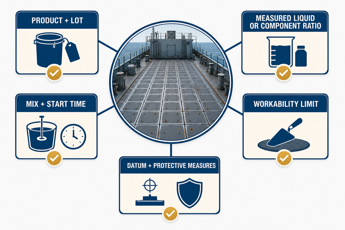
For each batch, provide measured inputs, work front and elevation, and supporting evidence. Identify product and lot, mixer, required liquid or component ratio, mix time, start time, workability limit, ambient conditions, datum plan, and protective measures. Don’t adjust consistency by eye or retemper material unless the current instruction allows it.
For example, the July 2024 Sikafloor Marine-107 data sheet lists 6.5–6.8 L of water for a 12 kg bag, a 5–30°C substrate range and about 20 minutes of working time. These values belong to this product and revision of the data sheet. They aren’t a recipe for other types of cement mortar, polyurethane underlayment or Yibo model.
A different Mapedeck LiteScreed sheet describes a two-component polyurethane underlayment, a 4:1 mix by weight, no added water and application up to 20 mm. The PDF extraction was incomplete, so only these clean, bounded facts are used. Together, the two sheets clearly show the crew has to work according to the instructions of the product employed.
| Product-sheet control | Attributed example | Correct project use |
|---|---|---|
| Package identity | Marine-107: 12 kg bag | Confirm the actual package is 12 kg before applying its water range. |
| Water input | Marine-107: 6.5 L to 6.8 L | Measure within the stated 6.5 L to 6.8 L range; never copy it to a different product. |
| Substrate temperature | Marine-107: 5°C to 30°C | Record the actual value and verify that it remains between 5°C and 30°C for this example. |
| Working time | Marine-107: about 20 min | Size the crew and work front around the stated 20 min, not a generic shift plan. |
| Walk-on reference | Marine-107: about 3 hours at 23°C and 50% relative humidity | Treat 3 hours at 23°C and 50% relative humidity as a sheet-specific reference, not finish readiness. |
| Early protection | Marine-107: 12 hours | Maintain the stated protection for 12 hours and document any exposure. |
| Moisture before a dense finish | Marine-107: below 4% | Do not replace a measured result below 4% with a touch test. |
| Single-application depth | Mapedeck LiteScreed: up to 20 mm | Keep the 20 mm limit attached to that sheet; it is not a category-wide thickness. |
Match the work front to workability
Set datum points and finished-level requirements before placement. Align doors, penetrations, drains, thresholds, and transitions. Design the work front based on the mixing rate, crew size, placement method, and stated working time. An oversized pour results in uncontrollable edges and an uneven surface finish. An undersized pour can result in joints or feathered sections that the system prohibits.
Thickness is a controlled project variable, not a quality score. It accounts for the deck survey, specified elevation, product layer limits, and weight, strength, cure, finish, and approved build-up. “Thicker is stronger” and “lighter is better” are both unsafe shortcuts when those other variables are unresolved.
| Control type | Evidence to retain | No-go condition |
|---|---|---|
| Storage and conditioning | Delivery condition, storage record and conditioning status | Damaged packaging or material outside the stated storage envelope |
| Substrate release | Area boundary, preparation, repairs, condition and approval | Open repair, contamination or unverified retained coating |
| Material identity | Product, revision, lot and storage status | Unknown, damaged, expired or untraceable material |
| Mix inputs | Measured liquid/components, mixer and time | Unmeasured adjustment or wrong component ratio |
| Workability | Start time, work-front boundary and stated window | Expired material or unsupported retempering |
| Elevation and thickness | Datum readings, checks and area mapping | Layer outside the approved range or unresolved low/high area |
| Edges and openings | Stops, drains, thresholds, penetrations and transition details | Uncontrolled edge or blocked drainage path |
| Cure environment | Temperature, ventilation, protection, traffic and incident record | Unresolved water, heat, draught, impact or early traffic exposure |
| Next-trade release | Inspection, specified tests, repairs, deviations and sign-off | Open deviation or finish-readiness criterion not demonstrated |
Cure, Protection and Release to the Next Trade
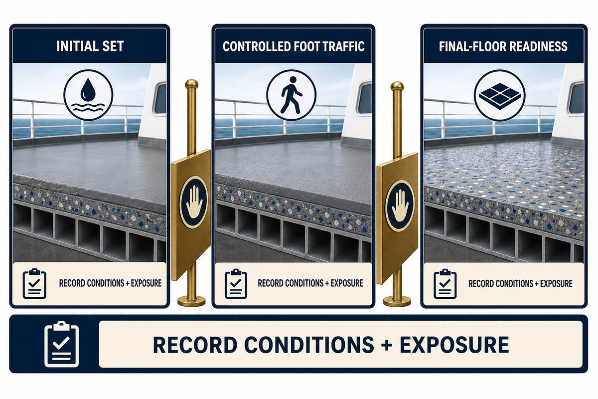
Initial set, controlled foot traffic, and readiness for the final floor are different release points. A surface can feel hard while moisture, strength or adhesion conditions may still be unsuitable for the next layer. Use the current product-system instructions and project procedure to set release criteria, and record temperature, ventilation, protection, and exposure.
The Marine-107 example lists walkability after about 3 hours at 23°C and 50% relative humidity, protection from direct heat, sun and draught for 12 hours, and moisture below 4% before dense flooring. These figures are attributed product examples, not performance promises for another project. Use the current product-system instructions to define the actual release criteria. A different space can have different weather conditions, ventilation, and material chemistry, which can lead to different release criteria.
Keep the area clear of unanticipated traffic, water, oil, grinding sparks, dust, impact, fast moving air, direct heat and other trades. When an incident occurs, capture its location, time, exposure, and disposition before anyone covers the surface. A finish-ready release cannot be inferred merely because no problem was reported.
Inspection and Handover Records

The inspection should relate the physical elements to the material and installation record. An appropriate handover will show the drawing boundary, date and work front, material lots, mixing record, environmental conditions, evidence of thickness or elevation, surface notes, repair map, specified testing, deviations and the party who’s authorized to lay the next layer.
Current eCFR rules on primary deck coverings approved by the US require annual inspections by independent labs and data packages with the manufacturer, product, date of manufacture and batch, and the type-approval number. Together, those records support the product-approval and traceability obligations. These don’t necessitate that every shipyard use this article’s handover template. The template below is a good intermediate step from product identity to area release.
| Record group | Minimum useful fields | Decision it supports |
|---|---|---|
| Area identity | Vessel, space, drawing, boundary, date, work front | Which surface was inspected |
| Material and mixing | Product, lot, inputs, times, mixer and crew | Traceability to installed batches |
| Conditions and geometry | Ambient/surface record, datum, elevation or thickness checks | Compliance with the project installation envelope |
| Surface and repairs | Cracks, dusting, contamination, edges, drains, repair closure | Whether visible deviations remain open |
| Release | Specified tests, references, exceptions, status and responsible sign-off | Whether the next trade may proceed |
Routine visual inspection typically addresses soundness, dusting, cracks, segregation, contamination, edges, transitions, penetrations, and drainage details. Only perform adhesion, moisture, hardness, density, or destructive tests when the approved inspection plan or current system calls for them. Without a matching method, product, substrate, and acceptance authority, quoting a generic test number may be worse than providing none.
Troubleshooting Cracks, Debonding and Uneven Areas
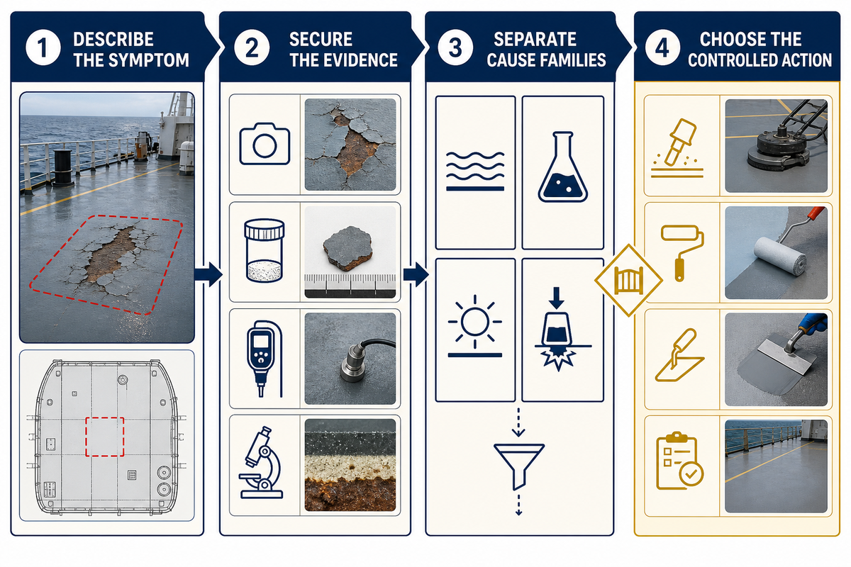
Cracks, a hollow response, surface dusting, delayed cure, and elevation misses are symptoms to investigate, not proof of a root cause. Preserve the area prior to grinding or patching. Document the size and the time of discovery. First map the affected extent and discovery time; then retrieve substrate and primer records, batch and mixing data, thickness or elevation checks, ambient history, early traffic or exposure, and the intended finish.
An official NAVSEA nonskid change rationale offers a useful shipboard analogy. It links oil and grease contamination with adhesion risk and reports small flight-deck nonskid areas that mud-cracked after normal application-condition requirements had been waived. Nonskid coating isn’t cementitious underlayment, so the case doesn’t diagnose a primary covering. It shows why contamination, conditions, repair extent and service criticality should be separated.
A second, explicitly analogous signal comes from a recreational boat-owner discussion: repair ideas began to be discussed while moisture and underlying structure were still being debated. The take-away is procedural: always inspect before a repair is committed to, and not a comment on shipboard screed causes.
Use the 4-Step Defect-to-Decision Framework
This framework creates a Defect-to-Decision Trace: the symptom, preserved evidence, tested cause families and authorized disposition remain connected instead of being collapsed into a repair guess.
- Describe the symptom. Map extent, pattern, depth, sound, strength, elevation and discovery time without assigning a cause.
- Secure the evidence. Preserve the records, photos and representative specimens before the area is disturbed.
- Separate cause families. Think about the substrate, compatibility, mixing, placement, thickness, cure/environment, and early service.
- Choose the controlled action. Isolate, test, accept, locally repair or remove only under the approved responsibility and method.
| Symptom | Evidence to collect | Cause families to test |
|---|---|---|
| Cracking | Pattern, depth, timing, thickness, joints, substrate movement, cure history | Movement, restraint, layer limit, mix variation, drying or early load |
| Hollow sound or debonding | Extent map, interface sample, preparation, contamination and primer records | Contamination, corrosion, incompatibility, open time or substrate failure |
| Dusty or weak surface | Batch inputs, finishing, exposure, protection and specified test result | Mix error, finishing, drying, water or chemical contamination |
| Delayed or uneven cure | Component ratio, batch time, temperature, ventilation and wet exposure | Incorrect ratio, incomplete mixing, cold/hot zones or contamination |
| Ridge, low spot or elevation miss | Datum survey, work-front sequence, workability and edge-control record | Survey, placement rate, flow, joint or finishing control |
Not every cosmetic blemish requires the same investigation as a widespread defect in a critical service area. Analyze extent, service, uncertainty, and the risk of covering the evidence. A local repair still needs compatible materials, a tie-in detail, cure protection and reinspection. When the defect challenges the approved build-up or repeats across batches, stop patching and escalate the system review.
The Five-Hold-Point Deck Readiness Loop
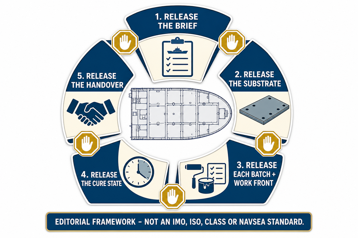
The Five-Hold-Point Deck Readiness Loop is an editorial project-control framework, not an IMO, ISO, class or NAVSEA standard. It gives engineering, installation and quality teams one sequence for deciding whether information and evidence are complete enough to proceed.
- Release the brief — confirm the space, substrate, layer stack, finish, acceptance route, schedule and unresolved interfaces.
- Release the substrate — close preparation, repair, condition, primer or bond-coat and datum questions before material is opened.
- Release each batch and work front — record material identity, measured inputs, timing, workability and elevation control.
- Release the cure state — verify time, environment, protection and incidents against the current system instructions.
- Release the handover — close inspection, specified tests, deviations and repairs before the next layer proceeds.
Give every hold point an owner, an evidence set and a no-go condition. The brief owner stops unresolved system scope. The substrate owner stops contamination, open repairs or missing datum. The batch owner stops unknown material, uncontrolled inputs or expired workability. The cure owner stops unverified exposure or damage. The handover owner stops open deviations or unclear responsibility.
The loop doesn’t standardize a percentage reduction in rework. Rather, it provides traceability. That record enables the next floor-covering trade to recognize that an upstream change has occurred. Before the final floor conceals an issue, isolate and review any primer change, moved datum, incomplete batch record, or area entered early.
From Educational Guide to Project-Specific Review
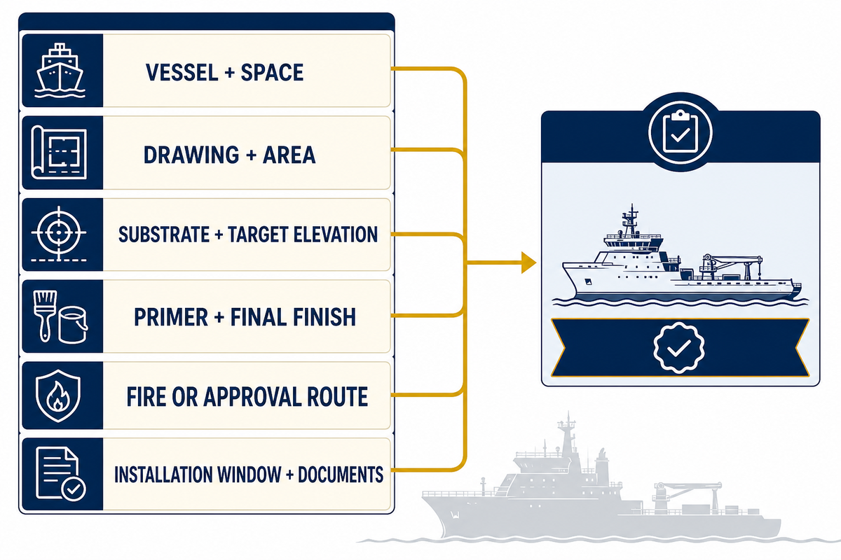
For a meaningful material review, submit the vessel and space, drawing, area, substrate, target elevation or thickness, primer or adhesive, final finish, fire or approval route, installation window, destination, and document requirements. This package gives a meaningful comparison and avoids the request becoming a generic “send price” request.
To view available data for the current model, certificate scope, project configuration, and quotation, click Yibo primary deck covering system options. Keeping commercial solution details outside this guide preserves its focus on education, process control, inspection, and diagnosis.
For examples of how vessel spaces change the flooring brief, use the marine flooring applications overview.
Bring the layer stack, not just the keyword
Send the vessel space, substrate, required elevation, final finish, acceptance route, schedule and document list for a project-specific review. Any company profile or certification statement should be checked against the current document pack for the selected system.
Primary Deck Covering FAQ
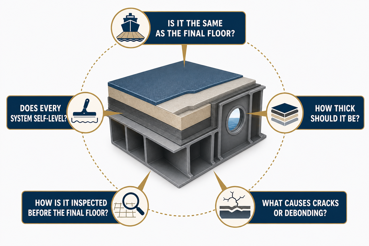
Is primary deck covering the same as the final floor covering?
No. Primary deck covering is the first floor-construction layer that’s applied directly over the deck plating and may include necessary protection or adhesion materials within its scope. The final floor covering is placed on top of it. That boundary matters here.
A decorative finish, tile, carpet, rubber sheet, acoustic system or exposed nonskid layer can have a different function and acceptance route, so drawings and purchase documents should name each layer separately.
Does every primary deck covering self-level?
Not necessarily. Some products are troweled or pumped, while others are designed to flow or self-level under particular conditions. “Primary” describes the position or function in floor construction, not one behavior of placement. The named product and system procedure still control placement behavior.
In such a case, confirm the current product sheet, crew method, work front size, edge controls, and the allowable range of layers prior to treating a material as self-leveling.
How thick should primary deck covering be?
No universal safe thickness exists. Thickness is determined by the deck survey, the required finished elevation, local highs and lows, the selected product’s layer restrictions, weight and strength, the final floor, and the approved construction. A thicker layer doesn’t necessarily mean stronger performance, and lighter products don’t always mean better performance. Record required elevations and check against the technical and approval documents that are current.
How do you inspect primary deck covering before installing the final floor?
Identify the specific area and the batches that were installed. Review the batch records and the environment. Examine the elevation or thickness records, the surface soundness, and check for cracking, dusting, contamination, edges, penetrations, openings, transitions, and drainage. Close each repair and record any incident that occurred while curing.
Adhesion, moisture, hardness, density, or destructive tests should only be conducted if they’re stipulated in the approved inspection plan or selected system. Compare every observation with the drawing and inspection plan, and record the method, instrument, sample location and result where measurement is required. An unresolved deviation prevents release; handover is specific to the inspected area, selected finish and next trade. Finish with a written release naming the responsible parties, exceptions and next permitted activity.
What causes cracks or debonding in a marine deck covering?
Possible cause families include substrate movement or contamination, corrosion, primer incompatibility, mixing error, expired workability, uncontrolled thickness, poor cure conditions, early traffic or later exposure. The visible symptom does not identify which cause family is involved. Diagram the defect, preserve samples and related documents, and obtain project-team approval before repair. Do not cover or disturb the area until the responsible project team has approved testing and repair. The symptom is evidence to preserve, not a repair instruction by itself.
References & Sources
- US Coast Guard, Finish & Furnishing materials (definition only; legacy test-part wording not used as current authority)
- 46 CFR Subpart 164.106, primary deck coverings
- ISO 5694:2023, Ships and Marine Technology, Deck Covering Underlay (public abstract)
- NAVSEA Standard Item 009-26, deck covering (US Navy work-item example)
- NAVSEA 009-32 Change Rationale (analogous nonskid evidence)
- Sikafloor marine-107 Product Data Sheet (product-specific example)
- Mapedeck LiteScreed Product Data Sheet (product-specific contrast)
- Amorim Cork Solutions River-Yacht Case Study (first-party project example)
Author: DD
Commercial marine flooring systems
Plan the deck build-up before the workfront is released.
Yibo manufactures commercial marine flooring systems in Suzhou for vessel projects that need a coordinated deck-covering, resin-floor, or acoustic-floating-floor build-up.
Review marine deck covering systems, marine resin floor systems, and marine acoustic floor systems against the vessel area and planned application sequence.
Project enquiry
Give the engineering team the inputs that shape the system review.
Include the vessel area, substrate or deck condition, intended floor build-up, fire or acoustic target, and project schedule so the enquiry can begin with the relevant deck constraints.
Send Your Deck Schedule


![Marine PU Floor: Selection & Installation [Guide]](https://yibomarine.com/wp-content/uploads/2026/09/marine-pu-floor-blog-featured-150x150.png)