Get in touch with Yibo Company


Marine PU Floor Guide for Shipyard Selection and Site Control

![Marine PU Floor: Selection & Installation [Guide]](https://yibomarine.com/wp-content/uploads/2026/09/marine-pu-floor-blog-featured.png)
Updated September 2026 · Author: DD
A marine PU floor is a polyurethane-resin floor system selected for a defined vessel area, substrate, exposure and approval route. The name defines a chemistry family. No individual layer is thereby proven suitable, watertight, slip-safe or accepted for the proposed construction.
The short answer
Select the installed assembly, not the label. Screen six project variables, define each layer and interface, release the deck before mixing, keep product timing separate from personnel re-entry, and preserve an evidence chain from batch to repair. Current product, safety and approval documents will dictate the final outcome.
This guide is for shipyard engineers, marine outfitters, naval architects, owner representatives, quality teams and procurement staff. It explains how to frame and control a project before model selection. Current system data, certificate scope, commercial configuration and quotation remain on Yibo’s marine PU floor solution page. Keeping that commercial intent in one place lets this article focus on education, installation control, inspection and diagnosis instead of competing with the existing page.
Use the guide as a record of coordination across design, purchasing, installation and quality control. This manual doesn’t replace the current technical data sheet, safety data sheet, approved construction, method statement, inspection plan, flag or classification requirement.
What a Marine PU Floor Is, and What the Name Does Not Prove
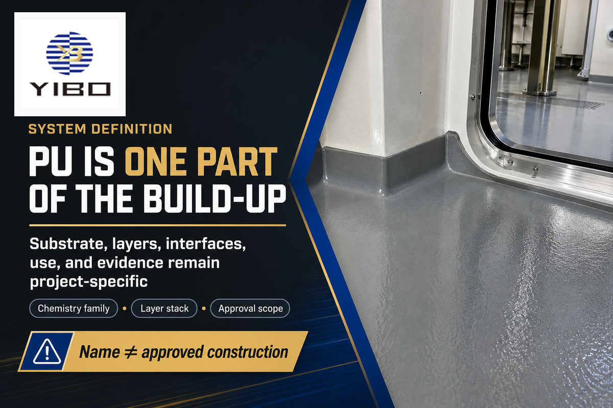
Typical use may include deck preparation, primer or bond coat, levelling or body layer, polyurethane wearing surface, topcoat application, and finishing of edges, drains and penetrations. These components describe a particular marine resin floor system; they must not be created from disparate data sheets.
The United States Coast Guard’s finish and furnishing guidance illustrates an important category boundary. It distinguishes a primary deck covering applied to deck plating from an exposed floor covering above it. Necessary primers, anticorrosive compounds or adhesives may belong to a tested primary-covering system, while a multi-layer exposed construction may require combination testing. That example isn’t a universal project rule, but it shows why “polyurethane” can’t describe the approval scope on its own.
| Statement | What it may tell you | What still needs evidence |
|---|---|---|
| “PU floor” | The system uses polyurethane chemistry somewhere in the build-up. | Exact layers, thickness, substrate, finish and compatibility. |
| “Marine” | The supplier positions the product for a marine context. | Vessel area, exposure, approval route and current document scope. |
| “Waterproof” | A documented layer may resist liquid water under stated conditions. | Continuity at drains, edges, penetrations, joints and repairs. |
| “Slip resistant” | A surface may have a tested or described texture. | Test method, contamination, cleaning, footwear, wear and slope. |
Key takeaway
The approval question is about a named construction and intended use. Never extend a result from one resin label, layer stack or test specimen to a changed assembly without evidence; related searches distinguish marine PU floor colors, IMO Marine flooring, PVC marine flooring and Impa vinyl flooring by project intent.
Use the Six-Variable PU Fit Screen Before Choosing a System
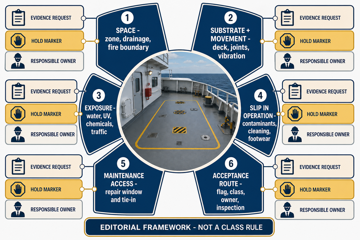
The 6-Variable PU Fit Screen
The Six-Variable PU Fit Screen is an editorial decision framework and not a class rule. This framework is meant to prevent procurement from choosing a material until the service brief is more definitive. Each variable must be supported by one evidence request, one hold condition and one owner.
| Variable | Evidence to request | Hold the decision when |
|---|---|---|
| 1. Space | Vessel zone, interior/exterior status, drainage, fire boundary and adjacent trades. | The same finish is being assigned to unlike spaces without a zone schedule. |
| 2. Substrate and movement | Deck material, retained coating, joints, vibration, thermal movement and repairs. | Compatibility or movement accommodation is assumed rather than detailed. |
| 3. Exposure | Water, ultraviolet light, chemicals, heat, mechanical traffic and cleaning agents. | “Marine grade” replaces the actual exposure list. |
| 4. Slip in operation | Likely contaminants, slope, cleaning state, footwear, texture and wear. | A dry laboratory or brochure label is being treated as every-use proof. |
| 5. Maintenance access | Damage scenarios, repair window, colour/texture matching and tie-in method. | A local repair would conflict with the assembly or close the space too long. |
| 6. Acceptance route | Flag, class, owner specification, approved build-up and inspection plan. | The certificate, test report or layer scope is unclear or outdated. |
Slip deserves special attention. The United Kingdom Health and Safety Executive describes pedestrian slip risk as a complex combination of parameters. It places surface contamination, contamination removal, cleaning, footwear selection and flooring choice among the controls. The Executive also notes that slipperiness can change after the floor is installed. Translate that principle into the expected shipboard operating condition. Don’t reinvent this page as a requirement for a marine test. Yibo’s hub for commercial marine flooring by vessel area and a project-specific exposure schedule are useful starting points.
PU, Epoxy or Another Covering? Compare the Decision, Not the Label
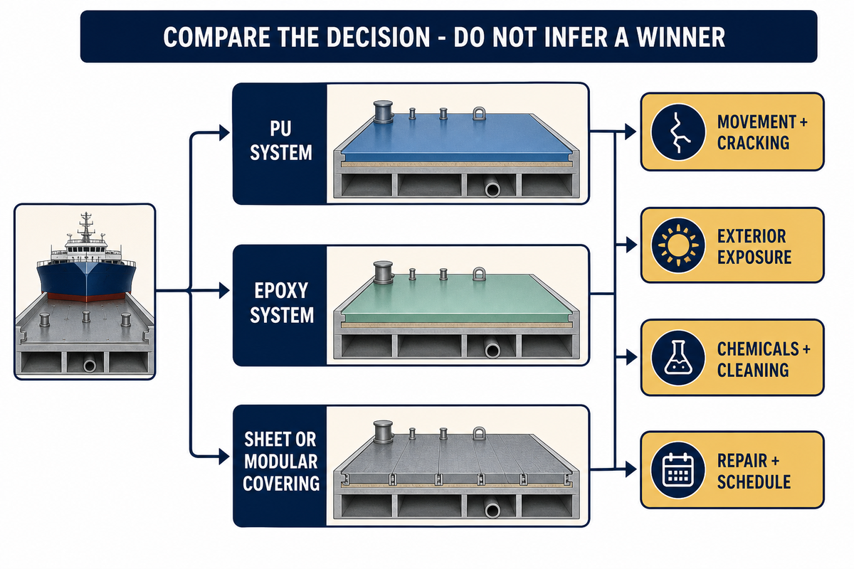
Neither polyurethane nor epoxy is superior. A polyurethane system may be considered where the documented formulation and build-up justify movement, finish, ultra-violet protection, and/or service requirements. An epoxy system may be considered where the documented hardness, adhesion, chemical resistance, and layer design are appropriate for the area. Review sheet or modular coverings where replacement speed, prefabrication or a different tested assembly matters.
| Decision input | What to compare | Do not infer |
|---|---|---|
| Movement and cracking risk | Substrate behavior, system elongation, joints and compatible layer design. | All PU is flexible enough, or all epoxy is too brittle. |
| Exterior exposure | Current finish/topcoat data, colour stability, water and weather details. | The resin family alone proves ultraviolet performance. |
| Chemicals and cleaning | Named substances, concentration, temperature, contact time and cleaning method. | “Chemical resistant” covers every spill or disinfectant. |
| Repair and schedule | Removal, tie-in, recoat window, cure, colour/texture match and access. | A fast surface cure guarantees a short shutdown. |
Use the same service description to review a marine epoxy floor system and any of the polyurethane alternatives. If the comparison alters the substrate, primer, finish, or evidence of approval, it’s no longer a resin-only comparison and is a different installed construction.
Supplier and search language may place flooring for ships beside Sika’s Sikafloor® Marine, paint, varnish, glue, a levelling agent or PVC products. Treat each as a label, not proof of property, excellent adhesion, elastic response, UV durability, slip-resistant performance, or the ability to withstand mechanical and chemical exposure.
Plan the Layer Schedule and Every Interface
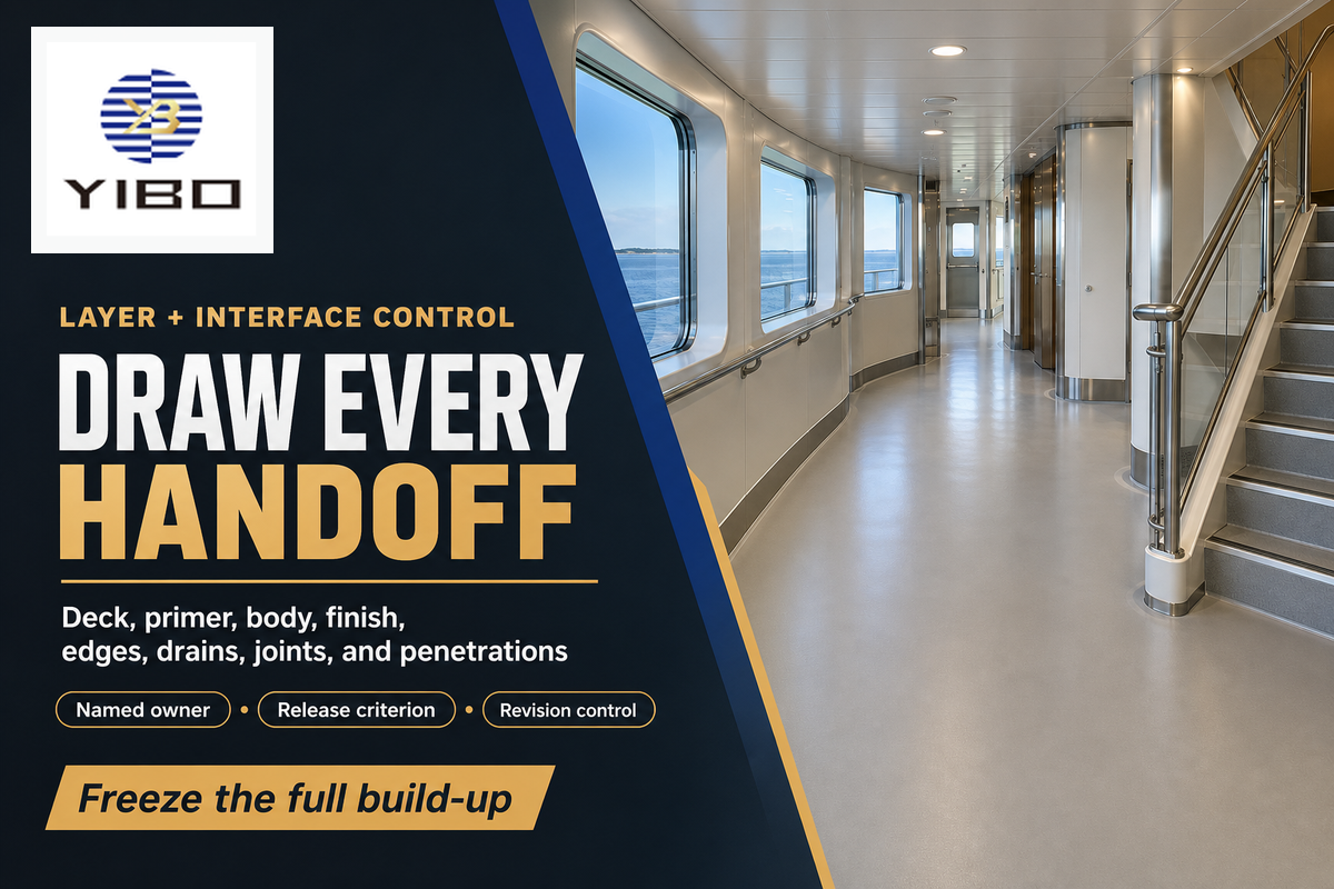
Even a suitable resin can fail as an installed floor when its interfaces aren’t managed. Put the build-up on a drawing or a controlled schedule: deck plating, retained protection, preparation, primer, body layer, finish, coving, edges, joints and drains, thresholds, penetrations, and adjacent materials. Define an owner and a release criterion for every interface.
Don’t interpret “self-leveling” as meaning that the material establishes all falls or finished elevations without survey control. A self-levelling deck covering may be an adjacent layer or alternative within a design, but the placement limits, edge restraints and compatibility are specified in that deck covering’s document. Likewise, a primary deck covering isn’t necessarily the polyurethane finish.
Interface register
- Who releases the substrate and retained corrosion-protection layer?
- What’s the primer or bond coat for the construction chosen?
- How are joints, drains, penetrations, coves and thresholds terminated?
- Which trade controls finished elevation and drainage falls?
- What happens if an adjacent material or layer revision changes?
As for one specific example of a regulatory definition, the current 46 CFR Subpart 164.106 considers approval as a defined product, intended use, and accompanying testing and inspection. The main point isn’t to use US terms liberally. Rather, it’s to maintain the proof that connects the installed layers to the route that was in fact used for the vessel.
Release the Deck and Environment Before Mixing
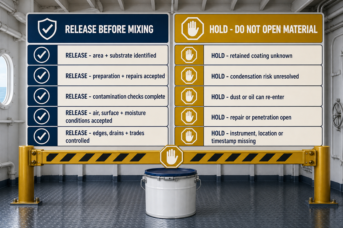
Make deck release a hold point. A surface that looks clean and dry doesn’t prove the required profile, absence of oil or salts, compatibility of retained coatings, surface temperature or dew-point margin. Ensure the selected method and acceptance source before the material is opened.
The significance of the current document is illustrated by the July 2024 edition of the Sikafloor marine-570 product sheet. This documents a 15–30°C application range with a requirement of substrate temperature at least 3°C above dew point. Those figures aren’t Yibo limits and shouldn’t be transferred to other formulations. They represent a measured value of a release variable.
Release when
- Area and substrate are identified.
- Preparation and repairs are accepted.
- Contamination checks are complete.
- Air, surface and moisture conditions meet the selected method.
- Edges, drains and adjacent trades are controlled.
Hold when
- The retained coating is unknown.
- Condensation risk is unresolved.
- Grinding dust or oil can re-enter the workfront.
- A repair or penetration remains open.
- The instrument, location or timestamp is missing.
Document the vessel, space, and boundary, as well as prepared substrates and repairs. Include environmental readings and instruments, the primer or bond-coat decision, document revision, photographs or inspection references, and the responsible release. The checklist is a control aid not a standard. The exact tests and limits are clearly defined in the project specification and selected system.
Control the Three Product Clocks, Then Verify Safe Re-entry Separately
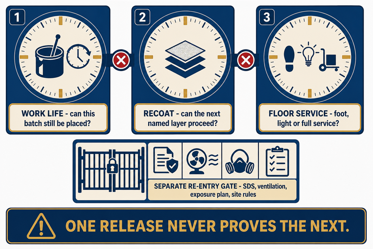
One time constraint can’t replace the many decisions that must be made during the process. The Three-Clock Application Control separates usable working time after mixing, readiness for the next compatible layer, and readiness for the stated floor service. Define each time with the batch, location, temperature, humidity, ventilation and current method.
| Clock | Question answered | Unsafe shortcut |
|---|---|---|
| 1. Work life | Can this mixed batch still be placed and finished as instructed? | Adding material or solvent to recover expired workability. |
| 2. Recoat | Can the next named layer be applied with the required preparation? | Using touch-dry appearance as bond evidence. |
| 3. Floor service | Can the floor accept the stated foot, light or full service? | Treating light traffic as full chemical or mechanical readiness. |
The Marine-570 sheet separates foot traffic, light traffic and full cure at 10°C, 20°C and 30°C. It also advises that uncured material must be shielded from moisture and condensation or water which can cause foaming. A second named sheet, Mapedeck LiteScreed, publishes a different 4:1 ratio by weight, 2–3 minute mix, 5–30°C application range and product-specific working window. These examples show variety; they do not recommend another product.
| Product control type | Marine-570 example | Mapedeck LiteScreed example |
|---|---|---|
| Mixing ratio by weight | 79:21 | 4:1 |
| Application temperature | 15–30°C | 5–30°C |
| Dew-point margin | Substrate at least 3°C above dew point | Substrate at least 3°C above dew point |
| Pot life at 10°C | 30 minutes | Not stated in this temperature-table form |
| Pot life at 20°C | 21 minutes | Not stated in this temperature-table form |
| Pot life at 30°C | 18 minutes | Not stated in this temperature-table form |
| Foot / light / full at 10°C | 24 / 48 / 72 hours | Use the stated project condition, not this row |
| Foot / light / full at 20°C | 18 / 24 / 60 hours | Use the stated project condition, not this row |
| Foot / light / full at 30°C | 16 / 18 / 48 hours | Use the stated project condition, not this row |
| Mixing time | 2 minutes, transfer, then at least 1 minute | 2–3 minutes for the stated mix procedure |
| Working time at cited build | Use the temperature-specific pot-life rows above | 1–3 hours at the cited 4–5 mm thickness |
| Single-lift thickness | Use the selected-system design | 0–20 mm |
Each entry in this table is related to its named September or July 2024 product sheet. This is variation, not a blended specification. Don’t average the ratios, times or temperatures, and don’t conclude that either product can be used on the Yibo project under review.
Temperature makes the control problem visible. In the Marine-570 example, pot life changes from 30 minutes at 10°C to 21 minutes at 20°C and 18 minutes at 30°C. Its foot, light and full-service sequence also changes: 24 / 48 / 72 hours at 10°C, 18 / 24 / 60 hours at 20°C, and 16 / 18 / 48 hours at 30°C. Mapedeck’s cited 1–3 hour working time applies at a stated 4–5 mm build. A recorded ambient temperature alone is therefore insufficient. Connect the reading to the surface, batch, layer thickness, clock being released and current product instruction.
Separate safety release
Floor cure doesn’t permit personnel re-entry. A NIOSH engineering-control page for MDI-containing spray-on polyurethane/polyurea work uses ventilation, access restriction, protective equipment, and exposure monitoring. That process differs from marine flooring, so its numerical limits aren’t transferred here. The correct approach is to employ the actual safety data sheet, application method, space evaluation, ventilation/exposure plan, and site rules. An occupational or environmental hold point can remain in effect when the floor achieves a product cure.
Inspect the Floor as a Record Chain, Not a Final Glance
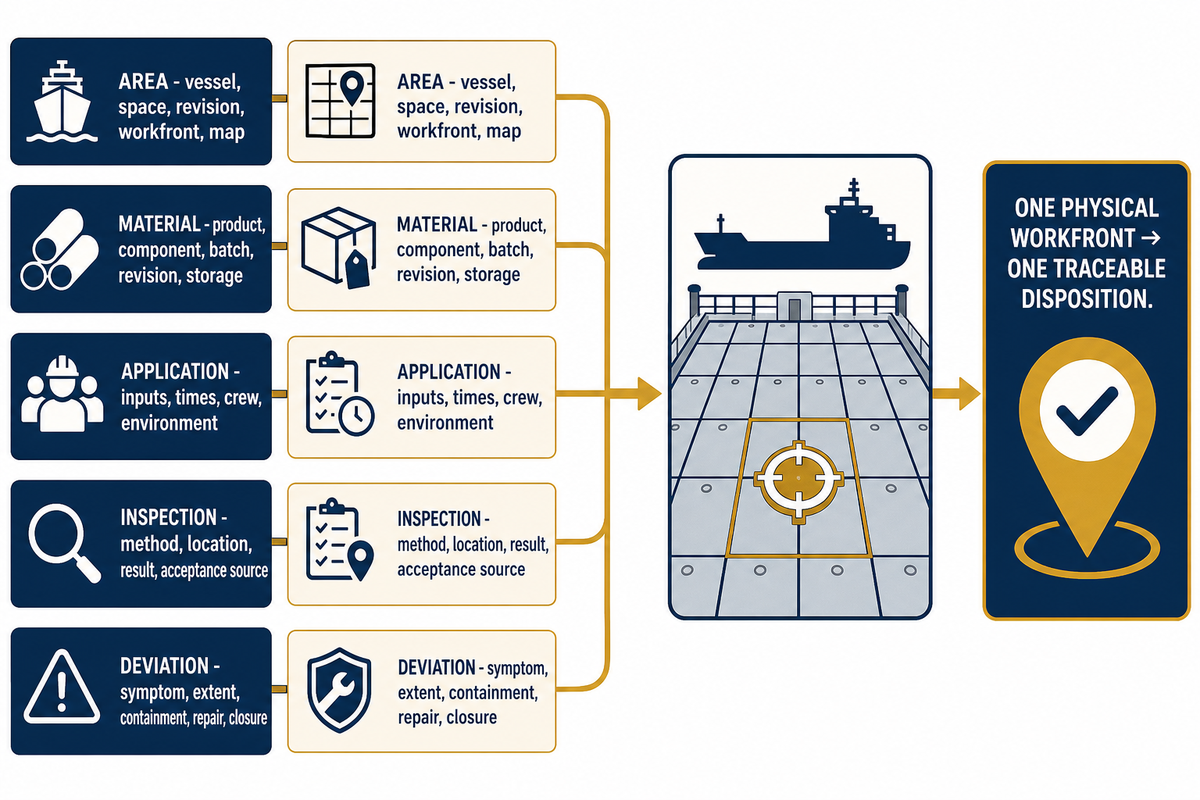
Smooth surface appearance is beneficial evidence but isn’t the complete acceptance record. Inspection should connect the physical area to product identity, batch, mix time, environmental readings, layer sequence, observations, tests, repairs and disposition. Without that link, we can’t connect a defect to a location or decision.
| Record group | Minimum useful connection | Decision supported |
|---|---|---|
| Area | Vessel, space, drawing revision, workfront and map. | What was installed and inspected. |
| Material | Product, component, batch, document revision and storage. | Which instructions and traceability apply. |
| Application | Mix inputs, times, crew, workfront and measured environment. | Whether the method stayed within its envelope. |
| Inspection | Observation or test, method, location, result and acceptance source. | Whether a layer or area may proceed. |
| Deviation | Symptom, extent, containment, repair and verified closure. | What changed and who accepted it. |
Scheduling visual checks and data for thickness, adhesion, hardness, holiday, slip, and cure tests should only occur if the project has a defined method and an acceptance criterion. Record instrument, environmental condition, and measurement location. An unsubstantiated measurement can lead to erroneous confidence. For design and preparation of the final document, the marine resin-floor document pack is the appropriate commercial handoff; the defined project authority has the final say on what should be provided.
Create the inspection map prior to taking samples. Break the work front by space and the installation sequence, batch, and known events rather than taking convenient samples after the floor is complete. Even if water entered one border, a mixer stopped during another batch, or a neighboring trade crossed one area early, these should be treated as distinct evidence. Results of other tests shouldn’t preclude localized exposure. One failed spot should trigger a local investigation and shouldn’t support a conclusion that the whole floor has the same cause. The inspection plan dictates the extent to which evidence can be generalized.
Diagnose Bubbles, Pinholes, Delamination, Soft Cure and Cracks
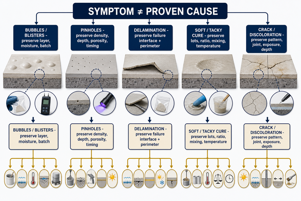
Visible defects are symptoms. Bubbles can indicate entrained air, substrate outgassing, moisture or poor application technique. A soft area can result from ratio, incomplete mixing, temperature, contamination or time. Delamination can be caused by the substrate, coating, primer, interface, contamination, movement or exposure to service. The appearance doesn’t help to distinguish among the causes.
| Symptom | Evidence to preserve | Cause families to test |
|---|---|---|
| Bubbles or blisters | Location, size, time, cross-section, layer, moisture and batch. | Air, outgassing, water, osmotic pressure, heat or technique. |
| Pinholes | Density, depth, affected layer, substrate porosity and application record. | Air release, sealing, viscosity, rolling or workfront timing. |
| Delamination | Failure interface, sound perimeter, retained coating and preparation. | Contamination, profile, primer, compatibility, cure or movement. |
| Soft or tacky cure | Component lots, ratio, mixing path, temperature and elapsed time. | Wrong ratio, incomplete mixing, inhibition, cold zone or contamination. |
| Crack or discoloration | Pattern, joint/detail position, movement, exposure and layer depth. | Substrate movement, restraint, thickness, cure, ultraviolet or chemicals. |
Start with six questions: where is it, how extensive is it, when did it appear, at which interface does it occur, which batches and conditions are linked, and what changed nearby? Make sure to separate your observations from your hypotheses. If the defect affects approval scope, a critical service area or multiple batches, widen the responsible technical review before local patching begins.
Use the Evidence-Before-Repair Ladder
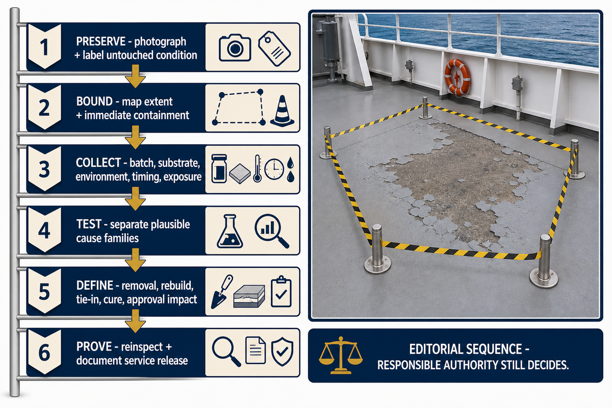
The Evidence-Before-Repair Ladder prevents an urgent repair from destroying the failure surface. It’s an editorial investigation sequence, and isn’t a replacement for a manufacturer, surveyor or project owner.
- Preserve — photograph and label the untouched condition, affected layers, boundaries and time.
- Bound — map visible and tested extent, service consequence and any immediate containment.
- Collect — secure batch, mix, substrate, environmental, timing, exposure and inspection records.
- Test — choose methods that separate plausible cause families instead of confirming one preferred story.
- Define — approve removal limits, compatible rebuild layers, tie-ins, cure controls and any approval impact.
- Prove — reinspect the repaired area and document service release, exceptions and future monitoring.
Local repair may be justified when the extent is bounded, surrounding material is sound, the cause is understood, the compatible tie-in is documented and the repair doesn’t invalidate the accepted assembly. Widen the scope when the cause is still uncertain, the defect repeats, multiple batches are involved, the substrate is moving or contaminated, or the approval construction may have changed.
Don’t expect the ladder to eliminate rework or find a root cause. Its value is decision traceability. The team can see what was noted prior to removal, the reasoning behind the selected repair boundary and the evidence supporting the floor’s return to service.
Traceability Is Established, Control the Current Evidence Chain
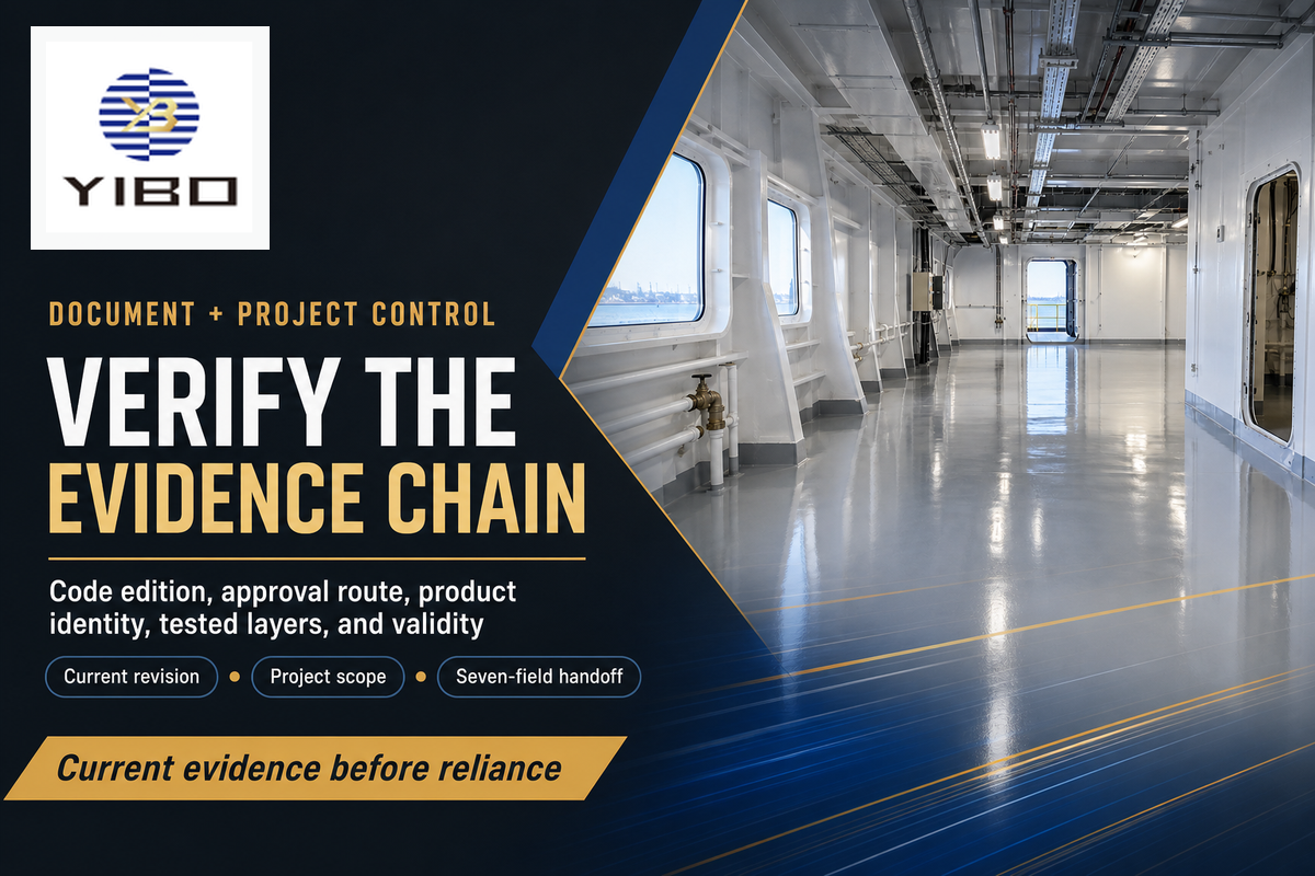
Laboratory testing and type approval aren’t new things. The International Maritime Organization considers the 2010 Fire Test Procedures Code an update to a regime from 1996. The current task is document control: verify the applicable code edition, administration or class route, product identity, tested layers and validity of the evidence used for this project.
Official IMO amendment listings and a 2025 United Kingdom treaty publication confirm that the broader framework continues to be maintained. Neither source provides a polyurethane-floor- specific rule change. The responsible action for a buyer is to investigate the currently applicable documents, rather than publishing an unsupported market-growth or regulatory-change claim.
Prepare a project brief without turning this guide into a quote page
Seven-field technical handoff
- Vessel, space and drawing revision
- Deck substrate, condition and retained layers
- Required build-up, elevations, falls and interface details
- Water, ultraviolet, chemical, traffic and cleaning exposure
- Finish, colour, texture and slip-use conditions
- Work window, ventilation, access and next-trade date
- Flag, class, owner and document/inspection requirements
Suzhou Yibo Industry & Trade Co., Ltd. states that it was founded in September 2001, operates from Suzhou and has more than 6,000 m² of company area, with ISO 9001:2015 quality-management certification at company level. Those profile facts do not prove the suitability or certificate scope of a particular floor. Submit the seven project fields so the proposed system and current documents can be reviewed against the actual vessel need.
Bring the operating brief, not just the resin name
Please provide the area, substrate, schedule of layers, exposure, finish, work window and route of acceptance. Once this information is received, Yibo can review the project against the current system without converting this educational reference into a quote or a price.
Marine PU Floor FAQ
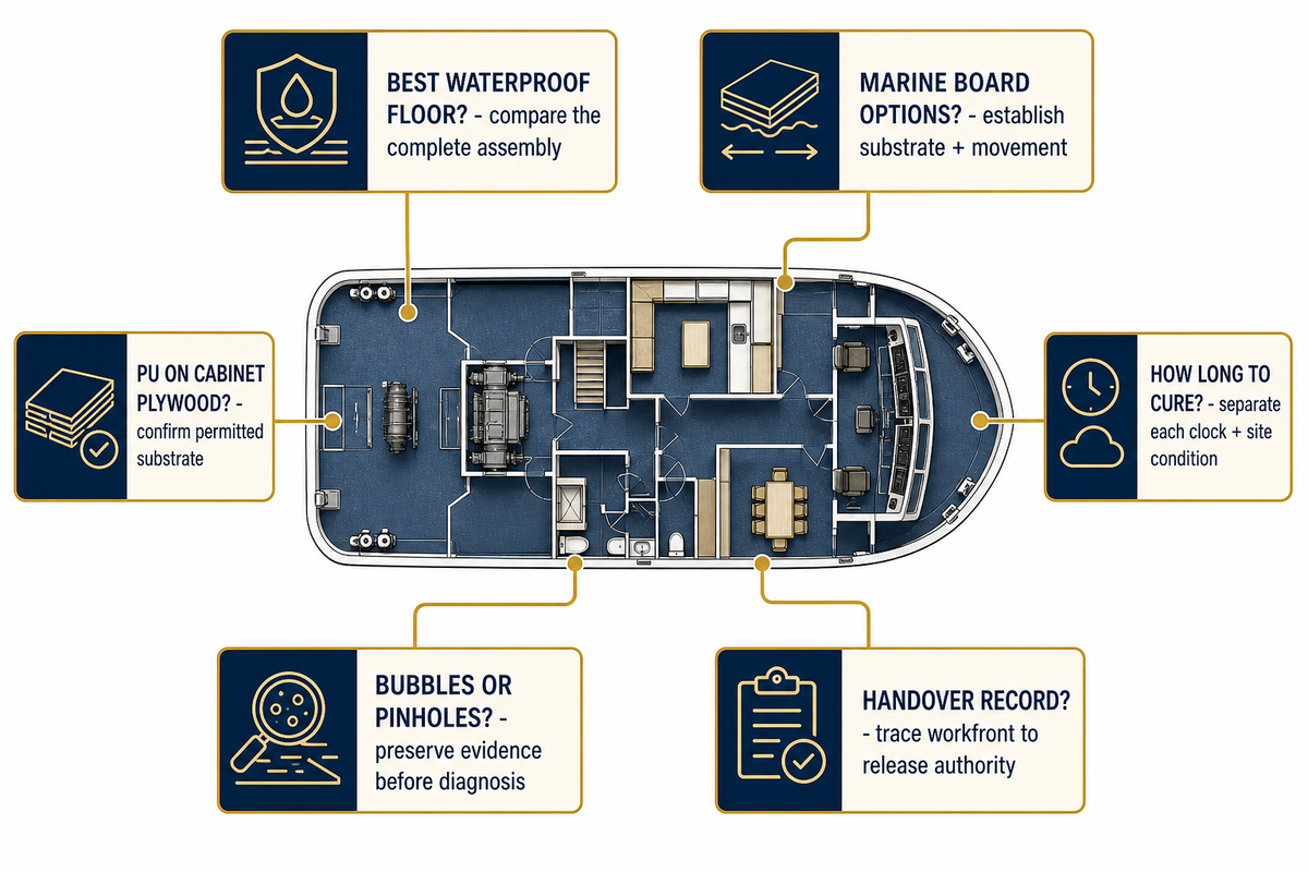
What is the best waterproof marine flooring for boats?
No single waterproof floor is best for every boat or commercial vessel. Factors such as substrate, deck movement, water exposure, edges, penetrations, drainage, traffic, cleaning and access for repair and the route for acceptance also influence the selection. Continuous polyurethane-resin surfacing may be one option, but “marine” doesn’t guarantee watertight construction. Compare the complete installed assembly and its current documents. This guide addresses commercial-vessel project controls; recreational-boat products may follow a different construction and evidence route.
Across the maritime sector, a yacht or working ship can combine indoor and outdoor zones exposed to sea water, sand, cutting dust, wood movement and different cleaning regimes. A global brochure cannot certify that a tailor-made installation meets every project obligation; each obligation belongs to the current product and project evidence.
What durable waterproof flooring options are available for marine board floors?
Marine board flooring often refers to leisure-boat plywood or board construction. This isn’t necessarily the same as a steel deck of a commercial ship. Resin systems, sheet materials, and bonded coverings may all be considered. Establish the board grade, condition, support, moisture on faces and edges, movement, detailing and fire route before comparing finishes. A statement concerning a resin surface can’t make up for an inappropriate or moving board substrate.
Can I use marine polyurethane on cabinet-grade plywood for flooring?
Just because a coating is labeled marine polyurethane doesn’t mean it’s a complete floor system on cabinet-grade plywood. Cabinet-grade plywood, structural marine plywood and a steel ship deck behave differently. Confirm the product’s permitted substrate and the applicable vessel construction before installation.
How long does a marine PU floor take to cure?
There’s no safe universal number. Working time, recoat readiness, foot traffic, light service and full service can happen at different times, and each can change with formulation, layer build, temperature, humidity and ventilation. Use the current product table and recorded site conditions for the exact decision. Separately authorize personnel re-entry under the actual safety plan; a floor cure doesn’t guarantee that the atmosphere is safe.
What causes bubbles or pinholes in polyurethane resin floors?
Possible cause families include entrained air, substrate outgassing, moisture, contamination, mixing, application technique and environmental conditions. Appearance alone can’t help select the cause. Preserve the location, cross-section, affected layer, batch and site records before grinding or filling the defect. Compare the pattern with mixing speed, wet-edge timing, substrate temperature, dew-point record and water exposure. Then choose a test that separates the plausible causes. Surface spot repair may address the symptom while leaving the primary interface condition unresolved.
What should be in a marine PU floor handover record?
Trace the area and build-up to substrate release, conditions, batches, application times, test methods, defects, repairs, disposition and the person authorizing the next state. Include document revisions, acceptance sources, inspection locations, repair closure evidence and the responsible release for each workfront.
References & Sources
- US Coast Guard, Finish & Furnishing Materials (category and layer boundary; legacy test reference not used as current authority)
- 46 CFR Subpart 164.106, Primary Deck Coverings (scoped United States approval example)
- International Maritime Organization, 2010 FTP Code Background
- International Maritime Organization, Amendments to IMO Instruments
- United Kingdom Government, 2025 FTP Code Amendment Publication
- United Kingdom Health and Safety Executive, Slip Resistance Improvements (general risk-control evidence)
- NIOSH, MDI Exposure Engineering Controls (analogous spray-process safety evidence)
- Sikafloor Marine-570 Product Data Sheet (product-specific example)
- Mapedeck LiteScreed Product Data Sheet (product-specific contrast)
Author: DD
Technical review: Suzhou Yibo Industry & Trade Co., Ltd. technical team
Commercial marine flooring systems
Plan the deck build-up before the workfront is released.
Yibo manufactures commercial marine flooring systems in Suzhou for vessel projects that need a coordinated deck-covering, resin-floor, or acoustic-floating-floor build-up.
Review marine deck covering systems, marine resin floor systems, and marine acoustic floor systems against the vessel area and planned application sequence.
Project enquiry
Give the engineering team the inputs that shape the system review.
Include the vessel area, substrate or deck condition, intended floor build-up, fire or acoustic target, and project schedule so the enquiry can begin with the relevant deck constraints.
Send Your Deck Schedule


![Marine PU Floor: Selection & Installation [Guide]](https://yibomarine.com/wp-content/uploads/2026/09/marine-pu-floor-blog-featured-150x150.png)