
Get in touch with Yibo Company


Cruise & Passenger Vessels are ships that carry passengers; for flooring planning, they need documented assemblies rather than finishes chosen from a color card. Effective planning connects each space to its substrate, build-up, interfaces, evidence, installation records, acceptance owner, and maintenance history. This method provides a cruise line and its cruise operators with a common brief while retaining vessel-specific review.
Quick planning brief
- Scope: commercial cruise ships and passenger ships, for newbuild and refit planning.
- Starting point: vessel applicability and a space-by-space area schedule.
- Core controls: interface ownership, deck release, traceable work fronts and change review.
- Acceptance: installed-condition evidence plus current product and project records.
- Boundary: no universal material, thickness, cure time or certificate is prescribed here.
Cruise & Passenger Vessels require space-specific flooring systems. The visible finish is one layer. Buyers should verify the full build-up, interfaces, applicable evidence, installation controls and handover records before selection or acceptance.
Key points
- A familiar surface label doesn’t reveal the hidden build-up or its approval scope.
- Physical interface ownership helps coordination, but it can’t replace fire, sanitation, accessibility, acoustic, safety or stability review.
- A crack, blister or stain is a symptom; preserve location and work records before deciding on a repair.
- Operating records from one voyage cycle can make the next refit brief more precise.
Updated September 2026. The applicability of this method will vary based on the type of vessel, flag, voyage or operating region, project status, and the governing agencies. The international cruise industry includes large ships, smaller cruise vessels, and other passenger ships that follow different governing paths. The relevant owner, shipyard, designer, class, or agency will determine the requirements.
What Makes a Passenger-Vessel Floor a System?

Passenger-vessel floors are coordinated assemblies that are suitable based on their installed locations and documented interfaces. Before reviewing any layer, stop and record the vessel type, flag, voyage or operating area, if it’s a newbuild or refit, and the parties responsible for design and acceptance.
That applicability stop is important because “passenger ship” is more general than “cruise ship.” For example, the official guidance for passenger vessels in the United Kingdom routes them to different standards based on the vessel type and the operating category. This national example isn’t a general rule, and it shows why a general checklist is insufficient for determining the governing path.
“A passenger ship is a ship which carries more than twelve passengers.”
The physical chain may start with deck steel and repairs, then move through surface preparation, a primary deck covering or underlay, a resilient or acoustic underlay where specified, adhesive, resin or finish, and the details around edges, drains, thresholds, penetrations and equipment bases. Acoustic performance can also depend on the wall-to-deck connection. Passenger ships and offshore work vessels can’t be considered equivalent categories.
The type and texture of the visible covering vary. Carpet, vinyl, tile, wood, resin and imitation teak systems can all be utilized. Levelling and/or damping layers can be installed beneath the visible systems. Some layers are poured, others come as sheets, tiles or components. ‘Poured floor’ thus refers to the application process and not all layers or all passenger spaces.
Applicability stop: if the vessel category, operating route, review authority or project stage is unclear, do not turn a generic layer sketch into a purchase specification. Resolve the governing route first.
The procurement team may object that this slows down material selection. However, recording five applicability fields at the beginning of the process prevents a later redesign from being regarded as a product failure. Within the given boundaries, the commercial solution page allows for the differing product families and currently valid documents.
Before comparing finishes, identify the vessel-application context. The same visible surface may lie over different assemblies and different routes of evidence.
Start With the Space and Its Service Conditions
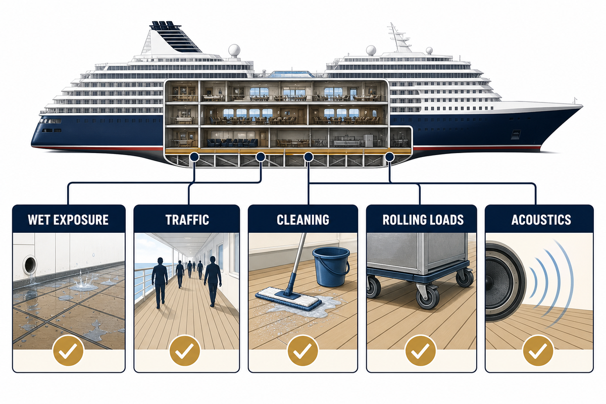
Space conditions should drive the flooring brief before a material name enters it. An area schedule connects location and use to wet exposure, traffic, cleaning, rolling loads, mobility needs, impact, acoustics, sanitation review, finish intent, replacement access, document route and an acceptance owner.
Each cabin has furniture. It also has bathroom and acoustic interfaces. Corridors and staircases add passenger circulation and transition details. Dining rooms or service areas add cleaning and sanitation questions. Open decks near the bow or stern face weather and ultraviolet exposure, while technical rooms add interfaces around access panels and equipment bases. The finish may need to withstand different traffic and types of chemicals in each zone.
Appearance, durability, reliability, and ease of maintenance belong in the brief, but each needs its own confirmation method. “Luxurious,” “lightweight,” “versatile,” “sustainable,” and “new” aren’t measurable targets for onboard suitability or versatility. Routes can become slippery after contamination or cleaning, even when dry samples feel secure.
The schedule which follows is a planning matrix, not a definitive materials list. Values such as slip resistance, layer thickness, moisture limit, or cure time must come from the selected project specification, product documentation, and competent review.
| Space or condition type | Evidence to collect | Planning effect | Escalation trigger |
|---|---|---|---|
| Wet route | Drainage, falls, cleaning and footwear context | Review water path and installed slip control | Standing water or route change |
| Cabin | Furniture, bathroom, acoustic and replacement interfaces | Coordinate finished height and access | Layout or threshold change |
| Corridor | Passenger flow, trolley traffic and transitions | Plan work-front isolation and edge details | Route cannot be protected |
| Staircase | Nosings, landings, lighting and cleaning method | Treat each transition as an interface | Geometry or visibility changes |
| Dining or service space | Cleaning chemistry, spill route and sanitation input | Review compatible finish and details | Chemical or use changes |
| Accessible route | Mobility-device use and applicable owner criteria | Coordinate stable route and transitions | Route or authority input changes |
| Lounge | Interior design, traffic and acoustic target | Separate appearance from performance evidence | Designer changes finish or build height |
| Technical room | Equipment bases, panels, fluids and access | Preserve removable and maintainable details | Equipment or exposure changes |
| Open deck | Weather, UV, drainage and thermal exposure | Review exterior system and water paths | New shade, pool or drainage detail |
| Refit access zone | Removal boundary, legacy materials and logistics | Set survey and safety holds before disturbance | Unknown existing layer |
The United States Centers for Disease Control and Prevention has a Vessel Sanitation Program construction activity for cruise-vessel construction and major renovation. This is a jurisdiction-specific, public health example that isn’t a global floor approval. Record it in the area schedule as a review-owner input where applicable.
The UK Health and Safety Executive also treats slip risk as a combination of floor, contamination, cleaning, footwear and installed condition. “Non-slip” or “non-skid” can’t replace route-specific evidence. Buyers asking for one universal value should define the operating condition and confirmation method.
Section takeaway: A ten-condition schedule transforms a broad interior design choice into a reviewable space brief without suggesting that every zone requires the same flooring.
Separate Performance Targets From Approval Evidence
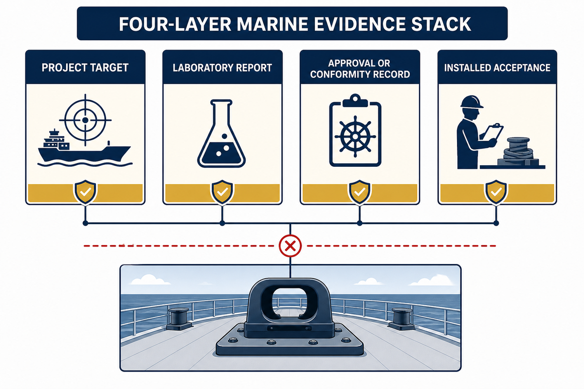
Performance targets, lab results, product approvals and vessel acceptance answer different questions. Disciplined review keeps four evidence layers separate: the project requirement, the test report, the current approval or conformity record, and the inspection or acceptance evidence for the installed location.
The International Maritime Organization (IMO) describes ship-level fire-safety objectives in its SOLAS chapter II-2 summary. This summary doesn’t certify or endorse a manufacturer, nor does it make one floor appropriate or suitable everywhere. The 2010 Fire Test Procedures Code includes testing and approval of materials and products for which the applicable requirements and limitations still need to be addressed.
The United States Coast Guard guidance provides a useful boundary for deck: primary deck covering is the first layer applied to deck plating, and everything above is considered floor covering, for the purposes of this approval. A multi-layer combination, along with its adhesive, can’t be treated as if it inherits the approval evidence of a single component.
| Layer | Question answered | Common error | Review action |
|---|---|---|---|
| Project target | What must the space achieve? | Copying a catalogue value without installed conditions | Bind target to space and acceptance owner |
| Laboratory report | What specimen and method were tested? | Treating a result as universal approval | Read specimen, method and conditions |
| Approval or conformity record | Which holder, product, application and limits are covered? | Using another product or expired scope | Check current identity, validity and limitations |
| Installed acceptance | Was the reviewed system correctly installed here? | Equating appearance with acceptance | Reconcile records, condition and interfaces |
For equipment coming under the European Marine Equipment Directive, the German Federal Maritime and Hydrographic Agency clarifies the wheel-mark and declaration. A general “EC” or “CE” statement can’t substitute for a certificate validity check of the related Marine Equipment Directive records and the product’s present scope.
Do
- Match the product identity and build-up.
- Read application limits and validity.
- Connect evidence to the installed space.
- Keep inspection and repair records.
Don’t
- Use ISO 9001 as product approval.
- Borrow a certificate from another system.
- Turn a customer relationship into acceptance proof.
- Assume one test covers every layer.
Yibo’s supplied company profile states that the company has passed ISO 9001:2015 and references SOLAS and several classification societies. Procurement should still ask for the latest record matching the selected product, build-up and application. Quality-management certification and a product or installed-system approval are distinct evidence types.
Section takeaway: four pieces of evidence answer four questions; bringing together these four pieces as a “certified” label removes the information the approver needs on scope.
Use the 9-Point Interface Ownership Map Before Work Starts
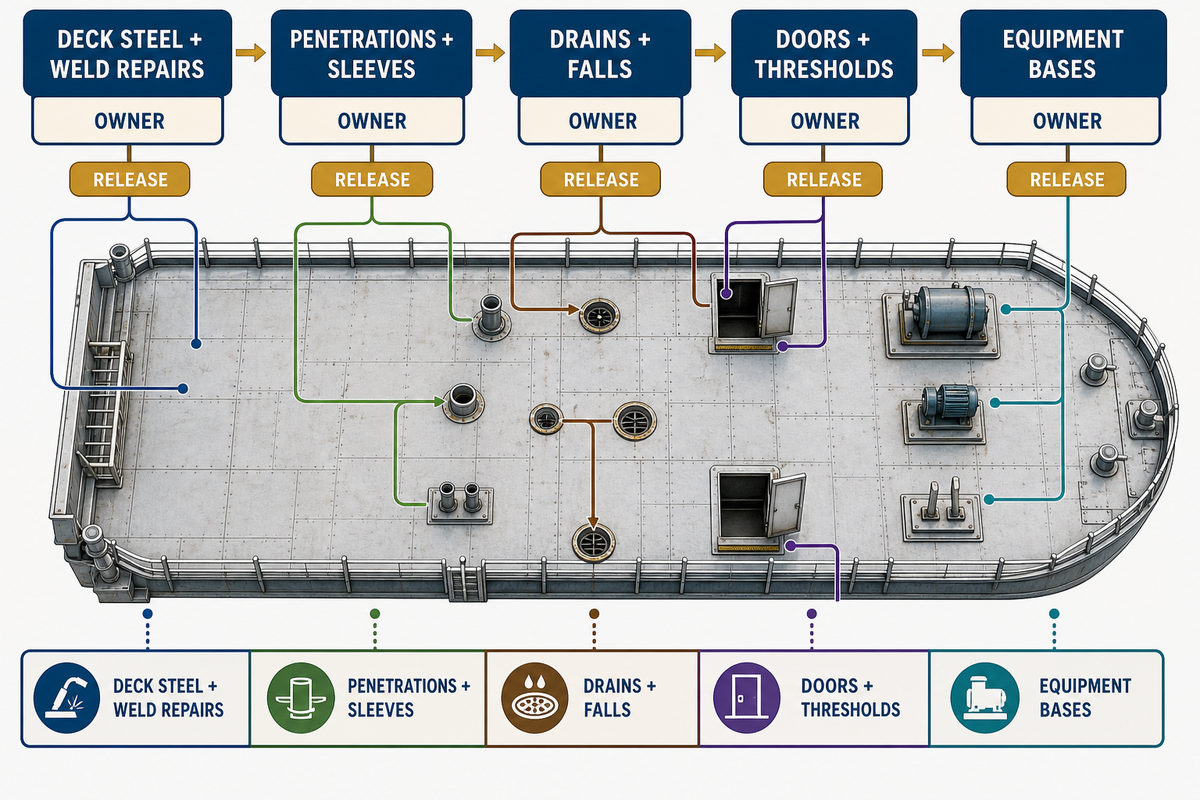
The Interface Ownership Map assigns each physical boundary to a design owner, evidence owner, installer input and acceptance owner before flooring work begins. It prevents unresolved deck, drain, threshold or penetration decisions from being silently transferred to the crew placing the final layers.
Interface Ownership Map. One table records who must answer each boundary question before release.
| Interface | Design owner | Evidence owner | Installer input | Acceptance owner | Release question | Escalation trigger |
|---|---|---|---|---|---|---|
| Deck steel and weld repairs | Structure | Shipyard | Preparation need | Named inspector | Is repair complete? | New defect or hot work |
| Penetrations and sleeves | System trade | System trade | Edge detail | Area owner | Is location final? | Late penetration |
| Drains and falls | Piping/architect | Survey owner | Achievable build | Wet-space owner | Will water reach drain? | Drain relocated |
| Doors and thresholds | Architect | Survey owner | Finished elevation | Area owner | Is build height available? | Tolerance stack closes |
| Equipment bases | Equipment trade | Equipment trade | Termination detail | Technical owner | Is footprint final? | Base moves |
| Removable panels | Access owner | Access owner | Edge and lift detail | Maintenance | Can panel be removed? | Access blocked |
| Vertical boundaries and coves | Architect | Area owner | Termination method | Finish owner | Is substrate continuous? | Wall build changes |
| Adjacent finish | Architect | Both trades | Transition profile | Area owner | Do elevations align? | Finish substitution |
| Stair landing | Architect/structure | Survey owner | Nosing interface | Route owner | Is geometry released? | Riser or nosing change |
When the levelling plan is approved, one option is to review a repositioned drain as an interface change. Flooring cannot determine the fall, piping cannot assume that the finish will absorb the change, and inspection cannot accept a route for water that was never checked. The map reopens the drawing, surveying, and approval of the wet space before the material is placed.
An example of a second situation is a door that doesn’t have sufficient finished height. Installing a thinner build-up might look like the fastest fix, but it can change layer compatibility, acoustic response, mass and document scope. The purchaser’s objection, “the finish still fits”, doesn’t address the system questions.
A ship cabin patent, which has been reviewed, includes the connections of walls, floor and deck as part of an acoustic system. The patent is in the recorded applicant’s context and is cited only to illustrate the system boundaries. The Interface Ownership Map is this guide’s editorial planning framework, not an external standard.
Section takeaway: nine mapped interfaces show unresolved ownership before these interactions result in site rework, while other competent reviews retain authority.
Release the Deck, Then the Build-Up
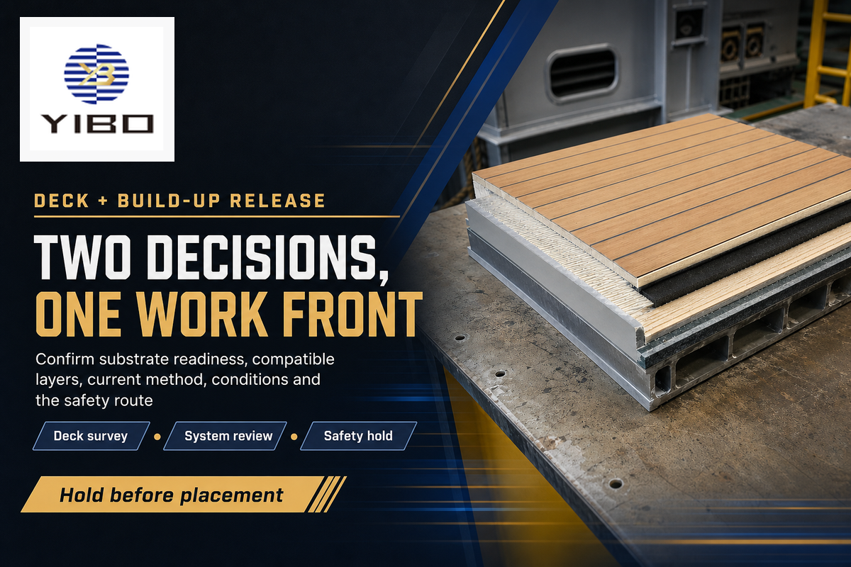
The release of deck and the release of build-up are two separate decisions. The first release indicates that the substrate and the adjacent work are ready to be prepared. The second release confirms that the current materials, compatible layers, method, environmental limits, elevation, cure sequence, and protection plan can proceed in that location.
Substrate review can cover contamination, corrosion, completed repairs, weld or grind condition, moisture, specified profile, dust or salts where applicable, penetrations, flatness, and elevation. Specific limits are described in the project specification and product method. Generic articles shouldn’t define universal moisture percentages, mixing ratios, or cure durations.
| Evidence available | Unresolved condition | Permitted next action |
|---|---|---|
| Deck survey and repair closeout | None within released area | Begin specified preparation |
| Survey incomplete | Unknown corrosion or elevation | Hold material placement |
| Current method and product records | Layer compatibility confirmed | Release the named work front |
| Finish sample only | Hidden build-up not defined | Complete system review first |
| Environmental record | Outside product or method limit | Hold and obtain disposition |
Safety Hold Before Disturbance. Suspected legacy hazardous material stops this quality workflow. UK Maritime and Coastguard Agency guidance says presumed asbestos should be identified before maintenance or structural alteration. This doesn’t formulate a general practice; it shows the reason the safety process of the competent shipyard must take precedence over scraping, grinding or removal.
Specified solvent-bearing coatings, adhesives, or resins can also invoke ventilation, testing, and stop controls under United States shipyard rules. The material and jurisdiction are the determinants of the procedure. Quality checklists shouldn’t allow clear records to override potential atmospheric hazards.
Section takeaway: release the physical deck before releasing the material system, and route any safety uncertainty outside the quality workflow before disturbance.
Control Installation in Traceable Work Fronts
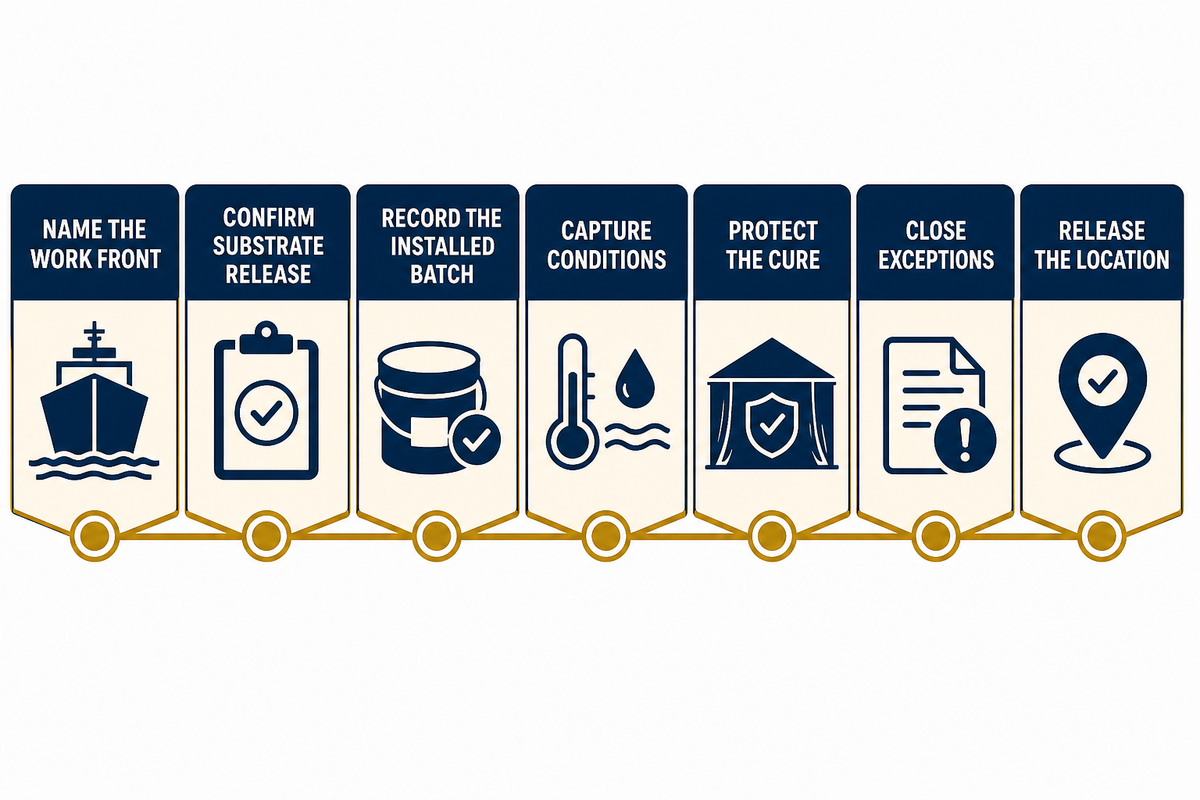
Traceable work fronts are bounded locations completed within recorded time windows. It isn’t a deck described after the fact. Its record links substrate release, product and batch, mixing, ambient condition, work time, measured build where required, repair notes, protection, inspector and release decision.
Records at a compartment level help answer later queries. Should one section show a soft spot, the team can compare that location to adjacent batches, readings taken from the environment, protection incidents, and the history of repairs. A record can show an exception that’s local or a repeated pattern that isn’t grounds for condemning every floor installed.
- Name the work front — bind the record to a space, boundary and planned time.
- Confirm substrate release — attach the accepted survey or hold-point record.
- Record the installed batch — capture product identity, batch and compatible-layer references.
- Capture conditions — use the product method’s required environmental and timing fields.
- Protect the cure — record access limits, adjacent trades and any wet-cleaning risk.
- Close exceptions — identify repairs and their acceptance evidence.
- Release the location — name the inspector, result and next permitted trade.
Compressed dry-dock windows create a familiar access conflict. The floor needs protection, while other trades e.g. hotel, electrical, and furnishing need access. Using seven steps doesn’t add cure time, but it tells the coordinator which route is closed, which area can receive the next trade, and who accepted an exception.
Continuous safety measures remain separate from the flooring quality record. Where a material or task requires ventilation or atmosphere testing, the competent safety process decides whether work may continue. The flooring record starts again only after the hold is cleared; “all fields completed” is never a permit to work.
Purchasers may say that compartment records create more paperwork. Bounded diagnosis is the counterpoint: one area ID, one batch, and one protection event cost less to investigate than an undocumented whole-deck claim. Traceability improves reviewability; it doesn’t ensure performance.
Section takeaway: Seven sequential records connect each installed location to its inputs and exceptions, so subsequent inspection begins with evidence rather than memory.
Use the Change-Control Trigger Card
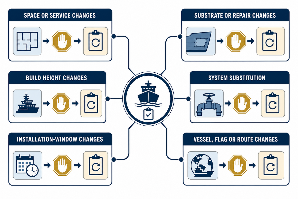
The Change-Control Trigger Card reopens evidence when a field that supported the accepted build-up changes. Eleven trigger groups cover service, substrate, height, substitution, exposure, timing, documents, vessel applicability, safety status, specialist inputs and cumulative mass or centre-of-gravity review.
Change-Control Trigger Card. Triggers are questions to reopen, not automatic claims that every change demands the same class action.
| Trigger | Evidence reopened | Parties notified | Hold condition | Closure record |
|---|---|---|---|---|
| Space or service changes | Area schedule | Space and floor owners | New use unreviewed | Revised schedule |
| Substrate or repair changes | Deck release | Structure and installer | Repair incomplete | New survey |
| Build height changes | Section and interfaces | Architect and trades | Threshold conflict | Accepted section |
| System substitution | Compatibility and approval | Design, supply and acceptance | Scope not matched | Approved substitution |
| Cleaning or chemical changes | Exposure and maintenance method | Operations and supplier | Compatibility unknown | Accepted method |
| Installation-window changes | Cure and protection plan | Planner and adjacent trades | Protection cannot be held | Revised work-front plan |
| Document-scope changes | Test and approval file | Document and acceptance owners | Identity or validity mismatch | Current matching record |
| Vessel, flag or route changes | Applicability basis | Vessel compliance owners | Governing path unclear | Reconfirmed basis |
| Legacy or atmosphere status | Hazard and work controls | Competent safety owner | Safety uncertainty | Safety release |
| Sanitation, accessibility or acoustic input | Space-specific review | Named specialist owner | Input unresolved | Updated acceptance input |
| Net mass or centre-of-gravity impact | Cumulative change assessment | Naval-architecture/stability owner | Impact not reviewed | Owner disposition |
A late request for a thinner build-up at a door may look local. The card reopens the section, layer compatibility, approval scope and acoustic input before the substitution reaches site. A changed cleaning chemical reopens exposure and maintenance evidence. A shifted installation window reopens cure protection and passenger-route access.
The card also catches changes outside the flooring contractor’s authority. If cumulative mass or centre-of-gravity impact becomes material to the vessel, the naval-architecture or stability owner reviews it. The card doesn’t publish a threshold or make that decision on their behalf.
Buyers may ask for approved alternatives in advance. A better rule implies that each substitution will require specific evidence, and states who will close it. Such a rule provides flexibility and allows adhesives, layers and certificates to be treated as distinct.
Section takeaway: eleven trigger groups stop a small field change from bypassing the evidence that made the original build-up acceptable.
Inspect the Evidence Chain Before Handover

At handover, reconcile the planned area, accepted system, current document references, substrate release, work-front records, cured observations, repair closeout, protection notes, and final index. Visual walkdowns are still necessary, but decorative surfaces can’t satisfy evidence for missing scope or interfaces.
| Item | Evidence | Owner | Acceptance question | Result |
|---|---|---|---|---|
| Area identity | Area schedule and drawing | Design owner | Does use match the reviewed brief? | Hold or release |
| System identity | Accepted build-up | System owner | Do installed layers match? | Hold or release |
| Product documents | Current product/test/approval file | Document owner | Do identity and limits match? | Hold or release |
| Deck release | Survey and repair record | Shipyard | Was substrate accepted first? | Hold or release |
| Installation | Work-front records | Installer | Are required fields traceable? | Hold or release |
| Cured condition | Inspection and test observations | Inspector | Does condition meet the named criteria? | Hold or release |
| Repairs | Defect and closeout record | Repair owner | Is every exception closed? | Hold or release |
| Interfaces | Map and as-built details | Interface owners | Are drains and thresholds resolved? | Hold or release |
| Protection and cleaning | Protection removal and maintenance notes | Area owner | Was the finish preserved? | Hold or release |
| Final index | Linked handover register | Document controller | Can each location be traced? | Hold or release |
The European Marine Equipment Directive governs product conformity documentation rather than this guide’s project-level substrate, installation-traceability and walkdown records. The accompanying declaration can support product identity and the applicable route, but it can’t replace substrate release, installation traceability, or a location-specific walkdown.
Stairs, dining spaces and wet passenger routes deserve location-based records. Critical detail is likely to be found at a nosing, drain, or other transition rather than in a field of a surface. If a buyer is seeking one global “floor complete” signature, the matrix offers a better option with ten reviewable objects and a named owner for each.
Section takeaway: handover connects what was specified, supplied, installed, repaired and observed; surface appearance is only one link.
Diagnose Symptoms With a General Triage Table
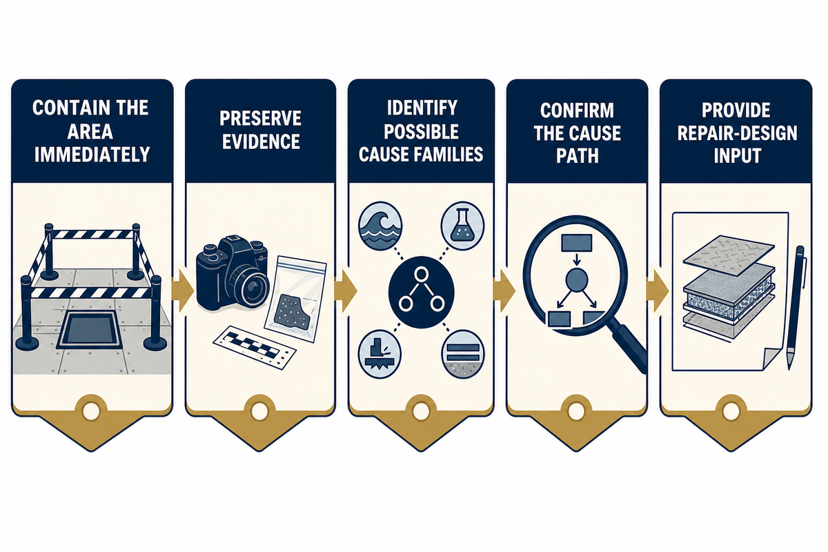
The diagnostic worksheet separates cracking, blisters, loose edges, softness and staining from diagnosis and treats them as observations. The order of action is to contain the area immediately, preserve evidence, identify possible cause families, confirm the cause path, and provide repair-design input. An overcoat should never be prescribed as a result of appearance.
Symptom-to-record triage table. Each row captures the evidence required to distinguish local damage from a reoccurring system condition.
| Symptom | Immediate containment | Evidence before disturbance | Possible cause families | Confirmation path | Repair input |
|---|---|---|---|---|---|
| Cracking | Protect route and mark extent | Location, layer, photos, movement history | Substrate movement, impact, cure or detail | Map pattern and inspect layers | Movement and termination detail |
| Blisters or bubbles | Limit traffic and water | Batch, timing, moisture and temperature record | Moisture, trapped air, contamination or cure | Compare affected and sound areas | Drying and layer compatibility |
| Loose edge | Remove trip exposure | Transition, cleaning and traffic history | Edge detail, adhesion, impact or water path | Inspect boundary and adjacent bond | New transition design |
| Soft or tacky area | Isolate and prevent contamination | Mix, batch, cure time and exposure | Mix/cure error or chemical interaction | Product-specific technical review | Removal boundary and cure method |
| Stain or discolouration | Stop unapproved cleaning | Chemical, water and UV exposure history | Maintenance chemistry, ingress or ageing | Review exposure and sample area | Cleaning or replacement scope |
| Persistent wetness | Control access and water source | Drain, falls, leaks and cleaning sequence | Drainage, ingress or operational water | Trace water path before opening layers | Drainage and waterproof detail |
| Delamination sound | Mark suspected boundary | Survey map and prior repair history | Bond, contamination, movement or water | Use agreed inspection method | Cut-out boundary and layer rebuild |
| Transition failure | Secure passenger route | Elevation, fastening and adjacent-trade record | Geometry, movement or impact | Recheck interface ownership | Revised transition assembly |
| Local wear | Monitor and protect route | Traffic, cleaning and replacement history | Use intensity, maintenance or material fit | Compare routes and service envelopes | Targeted repair or future brief |
When bubbles appear beside one wet-space drain after handover, cutting them open immediately may destroy the layer sequence, moisture boundary and contamination evidence. Evidence to preserve includes photos, the exact location, batch number, timing, ambient records, nearby work, cleaning history, and prior repair details. After that, the team can test theories of drainage, ingress, bond, and cure in an ordered sequence.
The same level of restraint should be employed in the slip investigation. HSE’s official statement links risk to surface, contamination, cleaning, and footwear as opposed to texture. Roughening a surface can accelerate the deterioration of the surface. Answer a request for a more aggressive non-slip finish with an operating-condition review, not a texture label.
When not to buy a quick overcoat: an overcoat should never be specified when the cause family or the underlying substrate conditions are unknown, the water path is unclear, or the layer is unknown. A new coating can hide the pattern and move the failure boundary. Preserve evidence, confirm the affected build-up, and design the repair around the cause supported by the investigation.
Section takeaway: nine symptom paths begin with containment and evidence; none treats appearance as a single-cause diagnosis.
Feed Operating Evidence Into the Next Refit
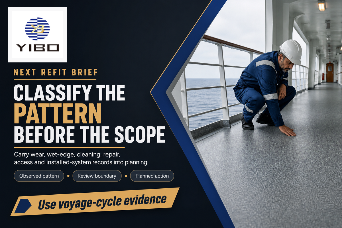
Operating evidence should update area schedules, removal boundaries, and work fronts for the next refit. Track recurring damage locations, cleaning difficulty, wet-route observations, edge and joint condition, repair frequency, access constraints and the installed system identity. This information will assist in the ordering of work based on evidence rather than guesswork.
A May 2026 Maritime Executive report, quoting Bolidt’s Jacco Smit, described the Allure of the Seas flooring work as lasting 43 days in dry dock and a further seven days at sea. The time reported for Allure of the Seas belongs to that example and isn’t a market average for such work. The real indication is coordination pressure: late scope work leaves limited time to complete the installation.
Before rolling a record forward, classify it. Planned replacement intervals may be justified by expected wear. Local abuse may indicate a protection or traffic control system. A failed drain edge can reopen an interface detail. Multiple batches or zones with repeated blisters may warrant a system-level investigation. Each of the cases described results in a different next step.
| Observed pattern | Next-refit input | Decision boundary |
|---|---|---|
| Predictable route wear | Traffic and replacement-access field | Confirm routine wear rather than bond failure |
| Recurring wet edge | Drain and boundary redesign review | Trace the water path first |
| Cleaning difficulty | Chemistry, texture and sanitation input | Do not promise easy maintenance from texture alone |
| Repeated local repairs | Expanded survey boundary | Separate recurring detail from whole system |
| Access conflict | Revised work-front sequence | Protect passenger and trade routes |
Proactive planning may extend service through targeted repair, prevent unjustified removal and define replacement scope through evidence. Without a verified lifecycle study or assessment, it shouldn’t be considered an emissions claim. The same should apply to “premium” or “durable” flooring language. The brief should reflect measurable outcomes of the project.
Turn Records Into a Review-Ready Flooring Brief
Include vessel type, flag, route, and project stage; an area schedule; substrate and quantities; section and elevation; drains, thresholds, and penetrations; service exposure; applicable safety, sanitation, accessibility, and acoustic inputs; the net-mass review owner; finish intent; installation window; and inspection and handover expectations. Teams ready to compare Yibo-specific build-ups and current documents can review its cruise and passenger vessel flooring solutions.
Key takeaway
A review-ready brief carries operating evidence into the next project while leaving product selection, current document scope and quotation to the commercial review.
Cruise and Passenger Vessel Flooring FAQ
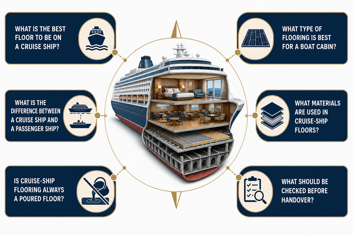
Most flooring questions have conditional answers because ship type, space, exposure, and approval route change the result. The answers below identify the next evidence to collect. They don’t recommend a universal material or declare a completed vessel compliant.
What is the best floor to be on a cruise ship?
Best flooring depends on the space and complete build-up
There’s no single best flooring for an entire cruise ship. A cabin, corridor, galley, wet route, technical room and open deck can have different traffic, acoustic, cleaning, exposure and replacement requirements. Define the space first, then review the full assembly, interfaces, applicable evidence and installation method. A luxury sample or material label can’t prove that fit. If the use changes, reopen the area schedule rather than assuming the original finish remains suitable. Final selection should follow the vessel-specific project brief and current supporting records. Compare alternatives against the same area schedule, then ask who owns each threshold, drain, penetration and maintenance condition. That comparison reveals whether a proposed surface solves the actual service problem or merely looks suitable in isolation.
What type of flooring is best for a boat cabin?
Treat commercial cabins differently from leisure boats
A commercial passenger-vessel cabin shouldn’t be specified in the same way as a small leisure boat. Review the steel deck, finished height, furniture, bathroom interfaces, footfall, cleaning method, acoustic target, fire-document route and replacement access. Carpet, resilient sheet, vinyl, tile, synthetic resin or another finish may work only within a compatible documented build-up.
What is the difference between a cruise ship and a passenger ship?
Passenger ship is the broader category
“Passenger ship” is the broader regulatory and operational category; the International Maritime Organization says such ships are usually defined as carrying more than 12 passengers. A cruise ship is organised mainly around leisure voyages and hotel-style spaces, while the broader passenger-ship category also includes ferries and related passenger services. Flooring still depends on the vessel’s governing route and each space.
What materials are used in cruise-ship floors?
Visible and hidden materials form one assembly
Cruise ship flooring can combine primary deck coverings or underlays, acoustic or resilient layers, adhesives, epoxy or other resin systems, carpet, vinyl, tile, imitation teak, wood, marble-look decorative finishes and protective surfaces. Not every material belongs in every space. The visible colour and grain don’t identify the hidden layers, compatible adhesive or approval boundary.
Is cruise-ship flooring always a poured floor?
No, poured layers are only one construction route
No. A self-leveling deck covering, damping layer or resin surface may be mixed and installed in place, while visible finishes can arrive as sheet, tile, carpet, imitation teak, wood or another system. Even a poured surface is one part of the complete assembly. Review the substrate, compatible layers, method, cured condition and edge details.
What should be checked before a passenger-vessel floor is handed over?
Reconcile the installed floor with its evidence chain
Check that the location matches the area schedule and accepted system; substrate and work-front releases are traceable; batch, mix, environment and build records are complete where required; cured observations and repairs are closed; interfaces are coordinated; and final product, test, approval and maintenance documents match the selected scope. Visual inspections alone are incomplete.
Section takeaway: a useful answer defines the space and evidence needed; it doesn’t transform a search phrase such as “best flooring” into a universal specification.
Prepare the right project conversation

Bring the vessel context, area schedule, interface details, operating exposure and required document route. Yibo can then discuss a project-specific marine flooring build-up without collapsing the technical review into a finish sample.
Editorial transparency: This guide separates general lifecycle planning from Yibo’s commercial solution page and product line review. Official and trade sources support the stated regulatory, safety and refit context. The Interface Ownership Map and Change-Control Trigger Card are editorial coordination tools, not external standards; the diagnostic table is a general worksheet. Company history and certification statements are labelled as supplied brand background.
References & Sources
- Passenger Ships International Maritime Organization
- Passenger ship construction and maintenance standards UK Maritime and Coastguard Agency
- Vessel Sanitation Program construction activity United States Centers for Disease Control and Prevention
- Slip assessment and improvement guidance UK Health and Safety Executive
- SOLAS chapter II-2 fire protection summary International Maritime Organization
- Approved equipment: finishes and primary deck coverings United States Coast Guard
- European Union approval of marine equipment German Federal Maritime and Hydrographic Agency
- Ship cabin acoustic arrangement, EP3956213A1 European patent publication
- MGN 669 Amendment 3 asbestos guidance UK Maritime and Coastguard Agency
- 29 CFR 1915.35, painting United States Electronic Code of Federal Regulations
- Directive 2014/90/EU on marine equipment EUR-Lex
- Refit projects and cruise-fleet renewal The Maritime Executive, May 2026


![Marine PU Floor: Selection & Installation [Guide]](https://yibomarine.com/wp-content/uploads/2026/09/marine-pu-floor-blog-featured-150x150.png)