
Get in touch with Yibo Company



Updated September 2026
Marine Acoustic Floor Systems are complete assemblies selected for defined vessel spaces, noise paths, operating conditions and acceptance requirements. It isn’t a single “soundproof” material. Results depend on the entire build-up and continuous control of the deck, perimeter, penetrations, thresholds, partitions and equipment interfaces.
Not every acoustic floor is a floating floor. Damping, resilient separation, added mass, load distribution, levelling and finish layers can perform different jobs, and none should be assumed to treat every airborne, structure-borne or impact route. A defensible project therefore follows a control chain: identify the path, freeze the inputs, assign each interface, protect the installation sequence, witness hidden work, read evidence within scope, investigate weak results by path and preserve the accepted construction through later refits. Project vocabulary can describe the build-up as acoustic flooring or a floating floor system, but a label does not establish noise reduction, structure-borne noise control or sound and vibration acceptance.
What a Marine Acoustic Floor System Has to Control
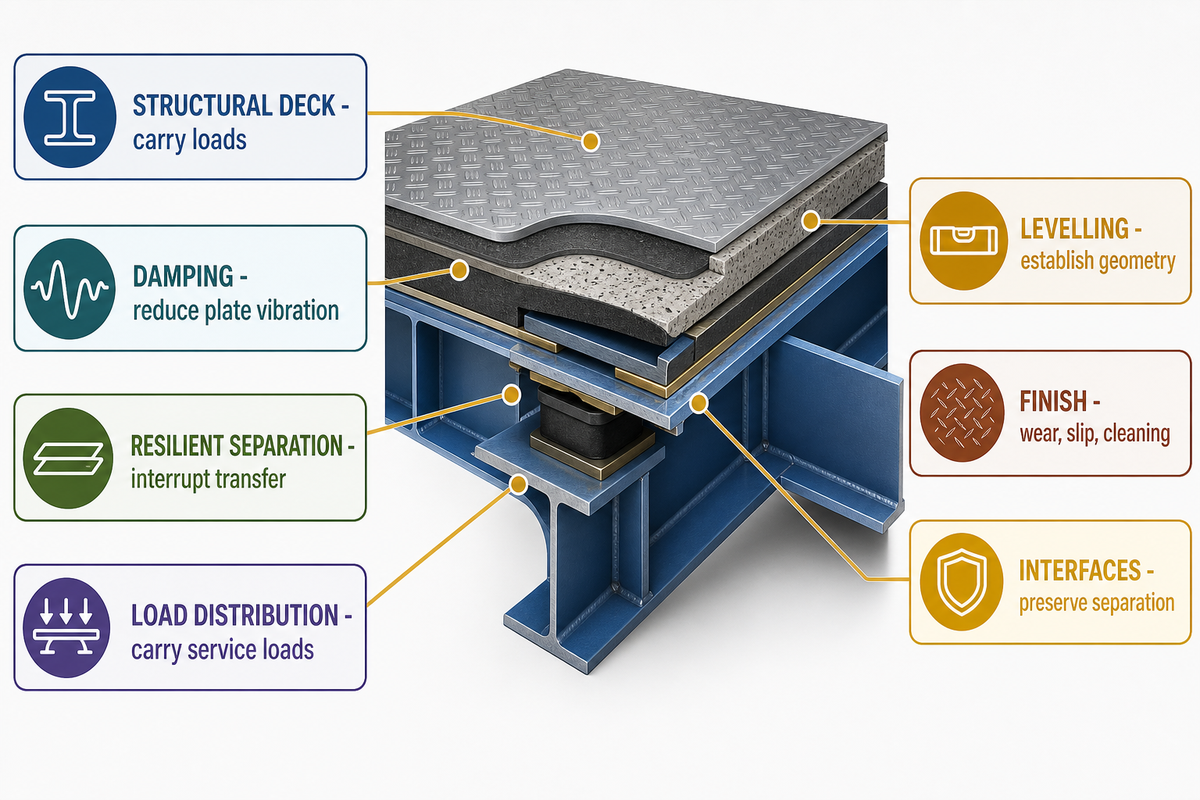
Begin with a design question other than “Which floor has the largest decibel figure?” It’s “What source is affecting which receiving space, by which route, under what operating condition, and against which criterion?” A propulsion or auxiliary machine may excite the ship structure. Speech or equipment noise may travel mainly through air. Footfall, trolley movement and other impacts may excite a deck directly. These routes can coexist, but a control measure that changes one route doesn’t automatically control the others.
At the base, the structural deck carries the loads. Damping may reduce plate vibration, while resilient separation may interrupt mechanical transfer. Load-spreading layers carry service loads above that separation. Levelling establishes geometry; a self-levelling deck covering is one product-family route, while the finish answers wear, slip, cleaning and appearance duties. Perimeter strips, collars and transition details protect the intended separation at the edges. Here, the system means the coordinated construction, not the most visible layer. A resilient element may use mineral fibre, an elastic or visco-elastic layer, or another specified compound; its job is not proven by the material name, and the completed assembly must remain resistant to the loads and exposures stated for the project.
Before applying a regulatory statement, determine whether the vessel is new or existing, its gross tonnage and ship type, whether the space is occupied by crew or passengers, the flag and project rules, and whether the provision is mandatory, recommendatory or informative. The International Maritime Organization’s Code on Noise Levels on Board Ships has defined applicability; it isn’t a blanket specification for every vessel and compartment. For passenger ferries, other ferry types or LNG carriers, the shipbuilding industry must still map the applicable IMO provisions to the vessel and space; a “fire rated” label cannot replace project technical specifications. Fixed-space results also differ from personal occupational exposure. As current maritime guidance in the United Kingdom states, exposure assessment relies on the level and time of sound within a work task, a daily or weekly exposure, rather than a single measurement in a space.
Evidence boundary: There is no universal thickness, weight, construction or sound-reduction value for all marine acoustic floors. Every number must remain attached to its specimen, method, metric, frequency range, boundary conditions and approval or project scope.
Trace the Noise Path with the Noise-Path Evidence Funnel
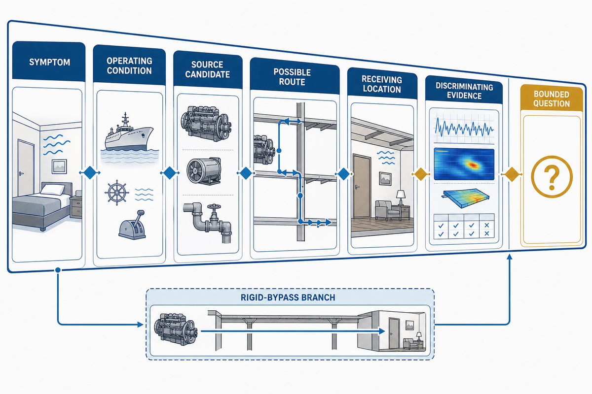
The Noise-Path Evidence Funnel is this guide’s editorial framework for narrowing an acoustic problem before product selection. It isn’t an International Maritime Organization, International Organization for Standardization or classification-society method. Its value is practical: each column forces a vague complaint to become a bounded engineering question.
| Reported symptom | Operating condition | Source candidate | Possible route | Receiving location | Discriminating evidence | Bounded question |
|---|---|---|---|---|---|---|
| Low-frequency cabin noise | Auxiliary set at named load | Machine or connected service | Structure, air or both | Berth and measurement positions | Operating comparison, spectrum, vibration and contact review | Does deck isolation address the controlling path? |
| Footfall disturbance | Single walker, passenger stream or trolley | Impact on corridor or deck | Local deck and connected structure | Space below or beside the route | Repeatable route, traffic case, time history and locations | Which assembly and interfaces reduce this excitation case? |
| Speech privacy failure | Normal occupancy and ventilation state | Adjacent room activity | Airborne, flanking or leakage path | Named receiver room | Partition, ceiling, door, duct and floor-edge observations | Is the floor edge material to the measured route? |
Impact excitation and walking excitation must be detailed as operating cases. Recently published ship research modelled time-varying corridor excitation and treated single-person and multi-person walking as separate cases. That work doesn’t prescribe a floor, but it challenges the assumption that one impact event represents all service traffic.
This funnel has a strict stop rule: if the source, route or acceptance criterion isn’t stated, don’t leap to a product and don’t add material “for safety.” Capture the observation that best discriminates between competing routes. Source shutdown may test one hypothesis. Contact inspection may reveal a rigid bypass, while a spectrum or vibration comparison may distinguish direct airborne sound from structural excitation. The next action should reduce uncertainty, not just add more bulk.
Freeze the Compartment Acoustic Brief Before Selection
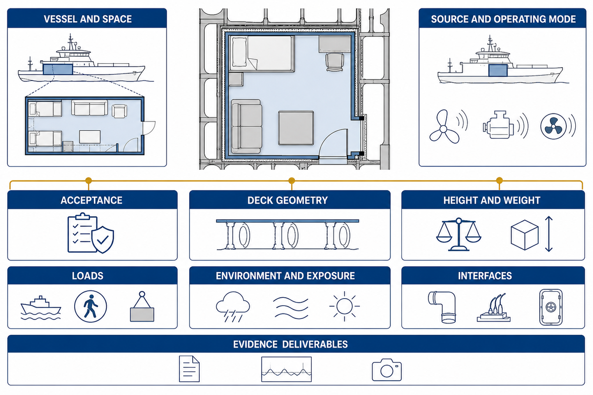
Compartment briefs prevent different trades from solving different versions of the same problem. Freeze the brief before selection and manage later changes by revision. At minimum, name the vessel type and build status, gross tonnage, compartment and adjacent spaces, source, operating mode, target metric, acceptance location, fire division, structural deck, available height and weight, imposed and point loads, finish, wet or chemical exposure, penetrations, boundaries, construction sequence and evidence deliverables.
The following table contains fictional values solely to illustrate record formatting. Those values aren’t acceptance limits, product data, design recommendations or evidence for any vessel. Replace each one with approved project information.
| Input type | Why it matters | Owner | Approved source and revision | Fictional format example |
|---|---|---|---|---|
| Source and operating case | Defines the excitation being treated | Owner, yard and acoustic specialist | Noise-control report | 600 rpm; 30 min; 2 hours; 1 day |
| Space and regulatory scope | Determines applicable duties and endpoints | Naval architect, flag and class | General arrangement and rules list | 1,600 GT; 6 months; 1 year; 2 days |
| Deck geometry | Controls available build-up and transitions | Structure and outfit disciplines | Coordinated detail drawings | 8 mm; 400 mm; 3 m; 24 m² |
| Height, mass and area | Tests the vessel envelope before selection | Naval architect and supplier | Weight report and approved schedule | 40 mm; 35 kg; 18 m²; 3 m |
| Loads and support zones | Defines service and point-load duties | Structural and outfit engineering | Load schedule and equipment plan | 300 kg; 2 m; 1 m²; 10 mm |
| Environment and exposure | Controls material and workfront conditions | Yard, supplier and safety team | Project procedure and product instruction | 20°C; 65%; 2 hours; 1 day |
| Acoustic evidence range | Binds observations to the relevant band and location | Acoustic specialist | Test plan and report | 63 Hz; 125 Hz; 250 Hz; 1.2 m |
| Penetrations and boundaries | Exposes rigid-contact and flanking risks | All affected installation trades | Interface register | 6 mm; 50 mm; 2 m; 12 m |
| Witness and handover timing | Defines how hidden work and exceptions close | Engineering and quality teams | Document register and inspection plan | 8 hours; 2 days; 6 months; 1 year |
Keep acoustic, fire, classification and quality-system evidence in separate fields. An approval given for fire alone cannot define an acoustic value. Management-system certification can’t prove the scope of a product approval, and laboratory results can’t prove that a later workfront matched the tested specimen. Separate fields ensure that one known document is not compelled to answer each question.
The brief should also record the controlling measurement method and the owner of each missing input. “To be confirmed” is meaningful only if it is owned, has a due date, and has a consequence of a decision. If a penetration layout remains open, for example, the floor detail can’t be treated as frozen simply because the layer schedule is complete.
This application-led brief gives marine flooring installers, interior contractors and offshore-vessel project teams the same revision basis. Lightweight options aren’t automatically suitable when their load, interface or evidence envelope differs from the approved case.
Assign Each Layer and Boundary a Job
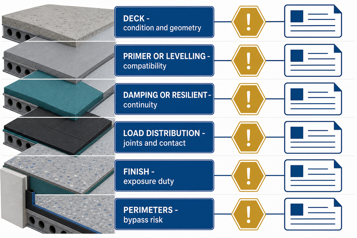
Role-based schedules are more informative than material lists. They explain why each component exists and what evidence would show that a substitution or site change has altered the design assumption.
| Role | Credible failure | Observable consequence | Document to check |
|---|---|---|---|
| Structural deck and preparation | Contamination, damage or unrecorded geometry | Bond, level or fit problem | Deck release and coordinated drawing |
| Primer or levelling component | Incompatible or outside approved envelope | Debonding, uneven support or cure concern | Approved build-up and product instruction |
| Damping or resilient element | Wrong material, compression, discontinuity or bridge | Changed vibration or isolation response | Assembly drawing, trace record and inspection |
| Load-distribution layer | Crack, joint error or unintended hard contact | Local damage, load path or bypass | Structural and installation details |
| Finish and exposure protection | Unsuitable duty or later damage | Wear, wet ingress or repair demand | Finish schedule and maintenance plan |
| Perimeter and penetrations | Rigid connection or flanking opening | Acoustic bypass despite correct central layers | Interface register and as-built detail |
A generic diagram explains a concept; it isn’t a certified construction. General changes such as substituting a resilient material, thickness, density, type and quantity of reinforcing, adhesive, topping, substrate, or joint and boundary detail, may take the work beyond the evidence envelope. The change may be acceptable, but it needs the appropriate engineering and approval review rather than an assumption of equivalence.
Install Without Reconnecting the Structure
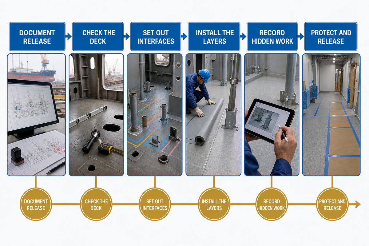
Installation can commence after the approved document set and workfront release are confirmed. Verify the assembly drawing, product instructions, material ID, compartment grid, hold points and trade boundaries. Then check deck geometry, cleanliness, retained coatings, welds, embedded items, penetrations, drains and adjacent work. A floor can’t protect an isolation line that another drawing has already contradicted.
Set out perimeters, thresholds, joints, openings and equipment zones before layers hide the structure. Install isolation details where the approved sequence requires them. Place each layer without tears, gaps, folds, unintended overlap, over-compression or contamination, following the current project method and supplier instructions. Maintain joint geometry, and don’t allow screws, mesh, reinforcement, temporary pins or tools to create an undocumented connection.
Interface completion requires coordinated trades. Different teams may install partition tracks, door thresholds, pipe and cable penetrations, drains, furniture bases and equipment supports at different times. Therefore, the floor contractor’s work boundary cannot delineate the end responsibility for acoustic. Every contact needs a detail, owner and inspection point before it disappears.
Retain material and batch identity, drawing revision, workfront location, date and installer. Record environmental or mixing data wherever the approved product instruction requires it. Take a photo of hidden interfaces with a stable compartment or grid reference. Log deviations at discovery, document the authorised disposition and verify correction before release. Located photographs tied to the exact boundary and inspection record are stronger than a folder of unlocated images.
After inspection release, complete the finish and protect the floor against traffic, wet work, hot work, dropped objects and later fixings. Temporary protection mustn’t become a rigid permanent connection. Control measures for safety related to handling, mixing, curing, re-entry and the use of personal protective equipment are bounded by the safety data sheet, the vessel approved documents, the project method statement, the permits and instructions from suppliers. An educational guide cannot authorize site work.
Run the Boundary Contact Walkdown Before Cover-Up
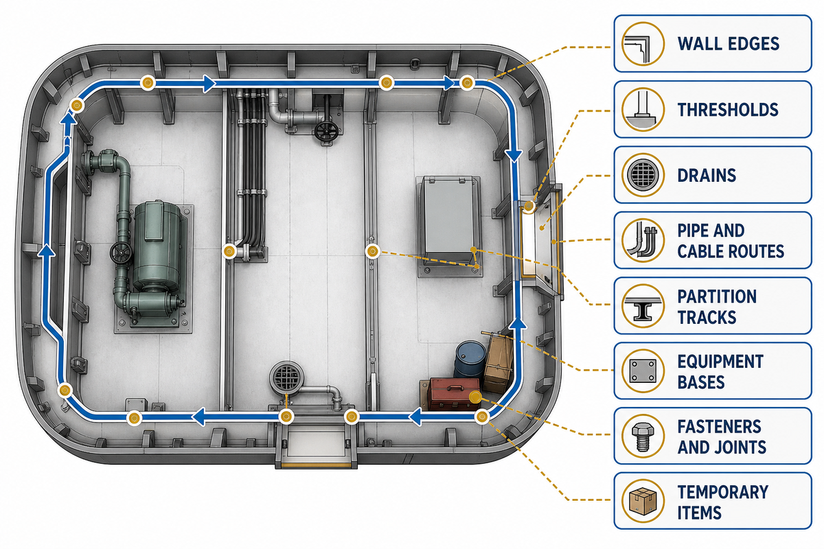
The Boundary Contact Walkdown is a structured pre-cover inspection for rigid bypasses and flanking routes. Walk the full perimeter of the compartments and every internal interface still correctable. The inspection is deliberately physical: drawings show intent, while the walkdown checks what is actually touching.
Examine wall edges, door thresholds, drains, columns, pipes, cable routes, partition tracks, equipment bases, fasteners and joints. Examine also temporary levelling aids, wedges, spacers, reinforcement tails, offcuts and other debris. Hard objects left across a resilient break can carry energy around the intended path. Open or poorly coordinated edges can also provide a flanking route even when the centre of the floor is correctly built.
At each location, ask four questions: What moves? What’s it touching? What will be hidden next behind it? Who owns the correction? Make a record of the compartment, grid or drawing, contact, trade responsible, final state, witness, photograph reference, and release. Don’t close an item with “checked” unless you can identify what you checked and where.
Boundary Contact Walkdown release rule
No boundary is released because the main floor area looks complete. Release follows a location-specific inspection of the approved detail, observed contacts, corrections and the next covering operation.
Owner and installer discussions about sound-control work often return to access, openings, removable panels and services. Such experience can improve the vocabulary used to anticipate coordination problems, but it isn’t performance evidence. Approved drawings and the project acceptance plan still decide what passes.
Verify Hidden Work and Read Test Evidence in Scope
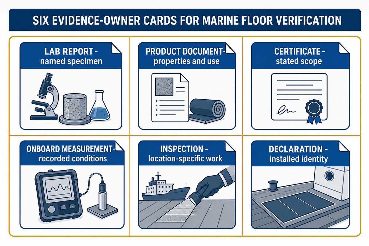
Evidence objects provide different kinds of data. Laboratory reports describe named specimens or build-ups under stated methods and conditions. Product documents define stated properties and use instructions. Certificates cover the holder, construction, test basis, validity and limits they name. Onboard measurements record the vessel, spaces, operating conditions, instruments, positions, method and result. Inspection records and declarations trace what was installed and accepted at specific workfronts.
Analyse evidence by owner, specimen or assembly, substrate, test method, metric, units, frequency range, boundary conditions, environment, revision and approval scope. An isolated high number isn’t automatically the more relevant number. A result obtained for one type of resilient material, topping, steel plate and boundary arrangement cannot be assigned to a change in construction without evaluating the evidence envelope.
Fire evidence must be addressed separately for each approval question. International Maritime Organization fire-safety material distinguishes smoke and toxicity, surface flammability, primary deck coverings and A-, B- and F-class divisions, among other topics. These aren’t interchangeable meanings of “fire certificate.” Determine which layer or assembly is being assessed, which test or approval route applies, and whether the installed construction remains within scope.
Keep space acceptance and personal exposure separate. Cabin or workplace results may establish compliance at the recorded location and operating state, but personal daily or weekly exposure also depends on the tasks performed, time spent in different areas and other noise events. Classification notations likewise need to be read by their stated endpoint. DNV provides COMF-V, VIBR and SILENT as distinct noise and vibration notations; one should not be substituted for the other.
The best evidence schedule is prepared before installation. It identifies which documents are informational, which require approval, which details require a hold point, who will witness them and how exceptions close. Evidence then becomes a production control rather than an archive assembled after the work is hidden.
Investigate a Weak Result by Transmission Path
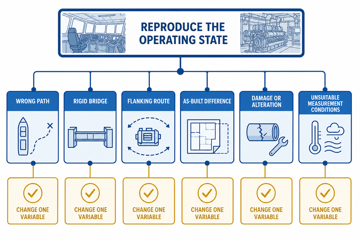
A weak onboard result doesn’t identify its own cause. Begin by reproducing the recorded operating state and checking that the test question, locations, background condition and instrumentation match the intended acceptance. Then separate six hypotheses: the control measure was fitted to the wrong path; a rigid bridge bypasses the resilient layer; a flanking route dominates; installed construction differs from the reviewed assembly; the system was damaged or altered; or the measurement conditions don’t support the comparison. Where an engine or thruster is suspected, change one controlled condition at a time to minimize confounding between the source, path and receiver.
| Symptom | Plausible route | Discriminating check | Bounded action | Verification |
|---|---|---|---|---|
| Local hotspot at an edge | Rigid contact or edge flanking | Compare detail, photograph and physical contact | Correct one identified interface | Repeat under identical recorded conditions |
| Broad change with machine load | Source or structural excitation | Controlled operating comparison and vibration path | Test the source-path hypothesis | Repeat at recorded load and positions |
| Result changed after fit-out | Later anchor, partition or service bridge | Review change records and boundary contacts | Remove or redesign the bounded alteration | Compare before and after under the same case |
Research on cruise-ship cabin noise supports separating machinery excitation, structural paths and cabin response. It isn’t useful to assign every weak room result to the floor. One bounded variable must be changed at a time. Multiple repairs conducted in parallel may improve the outcome, though they prevent the team from knowing which path was important and make it harder to trace the reason for the recurrence.
Protect Isolation During Maintenance and Refit
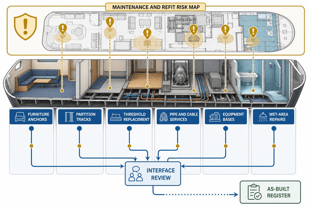
Later work can undermine an accepted floor. Furniture anchors, new partition tracks, threshold replacements, pipe supports, cable trays, drains, equipment bases and wet-area repairs can connect an isolated layer or create a flanking path. Thus, a small refit should trigger a review of interfaces, even in the absence of a replacement of the floor.
Change records must show the approved detail, the exact location, the proposed change, acoustic and the other duties impacted, the witness point, the repair instruction, the photograph, and the closure. Make the as-built interface register available to maintenance teams and show no-fix or controlled-fixing zones if possible. If a later team doesn’t understand why a resilient break exists, they may remove the detail that made the assembly work.
After damage or opening-up, restore the full duty, not just the surface appearance. Check resilient continuity and load path, water or fire boundaries, finish compatibility and any evidence that the alteration reopens. The repair is complete only when the changed interface is traceable and the appropriate inspection or test has closed.
Prepare the Submittal-to-Witness Chain for Handover and RFQ Readiness
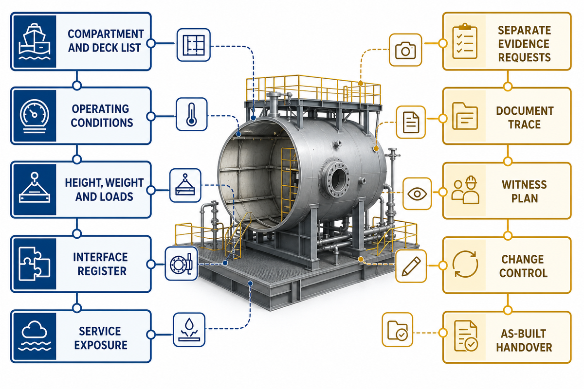
The Submittal-to-Witness Chain connects documentary intent to location-specific execution: requirement to approved document, material or batch identity, workfront, hidden-work witness, exception or disposition, acceptance result and as-built record. If one of the links is missing, the handover may present many documents which do not demonstrate that the reviewed construction was carried out in the mentioned space.
Before a commercial review is requested, a neutral evidence schedule should be prepared to include:
- compartment and deck list, including source and receiving spaces;
- operating conditions, acceptance criteria, method and responsible party;
- available height and weight, imposed and point loads, deck geometry and finish duty;
- boundary, threshold, penetration, partition and equipment-interface register;
- wet, chemical, temperature, cleaning and service exposure;
- separate acoustic, fire, class, flag and quality evidence requests;
- drawing, submittal, material-trace and workfront-record requirements;
- inspection and witness plan, including pre-cover hold points;
- nonconformance, repair, retest and change-control process; and
- as-built record format and maintenance handover.
Practical discussions about access and removable construction reinforce the need to document service interfaces, but they don’t set acceptance criteria. Approved project documents remain controlling. Readers who have completed the schedule and are ready to review available commercial configurations can visit Yibo’s commercial acoustic floor system range. That solution page owns product models, current specifications, certificate scope, comparisons and quotation; this guide remains the planning and control reference.
In the company profile supplied for this article, Suzhou Yibo Industry & Trade Co., Ltd. says it was founded in September 2001 in Suzhou, operates a facility of more than 6,000 square metres, supplies multiple marine floor and deck-covering families, and has passed ISO 9001:2015 quality-management certification. The supplied profile also describes collaborations with some major Chinese shipyards. These are attributed company-profile statements, not independently current-verified facts. They do not by themselves prove an acoustic result, a specific approval scope or an outcome on any named vessel; current project and approval documents must answer those questions.
Review Your Acoustic Brief with Yibo
Current Rules and Evidence Gaps: What They Do Not Prove
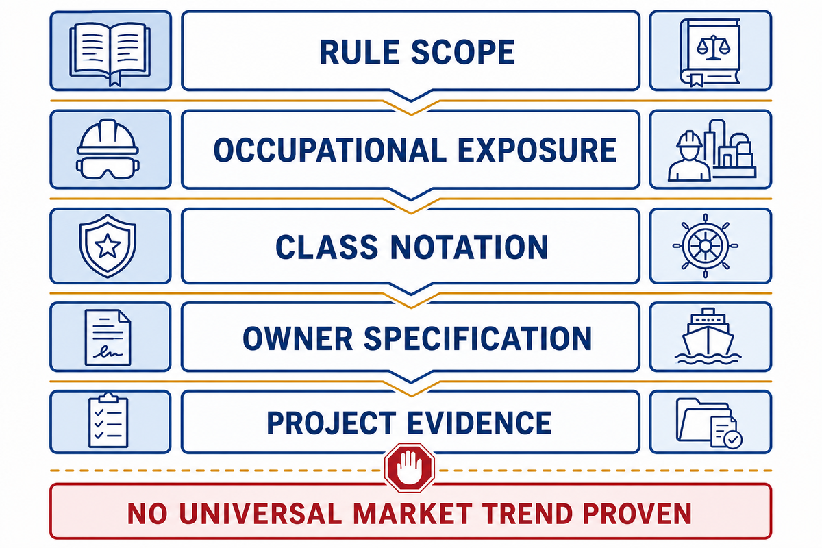
Current rules help define vessel scope, spaces, occupational exposure, acoustic endpoints and survey duties. These standards do not select a single floor. Determine whether the particular provision is mandatory or recommendatory and whether a class notation, owner specification, or national rule provides a different endpoint. Always verify the current edition and project applicability rather than relying on an undated summary.
International Maritime Organization guidance and action-plan work on underwater-radiated noise are separate from the policy and measurement context for onboard accommodation or workplace floor acceptance. That work isn’t a replacement floor-selection rule and shouldn’t be used to imply that an onboard acoustic assembly has newly required specifications.
The same fail-closed principle applies to market claims. Research for this guide found supplier material describing lighter floating-floor directions, but no transparent independent series that could establish a universal 2025–2026 market shift or saving. Market-forecast pages, undated supplier claims, search-volume anomalies and adjacent-building studies can’t establish a marine technical trend. Where the evidence stops, the article stops.
Frequently Asked Questions About Marine Acoustic Floor Systems
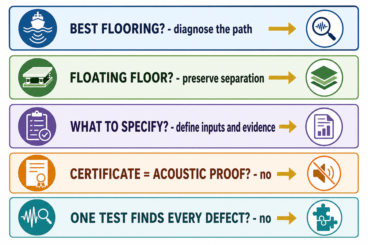
What type of flooring is best for soundproofing?
There is no universal best vessel floor; the right assembly depends on the controlling noise path, receiving space, operating condition, acceptance criterion and project constraints.
Start with the source, whether energy travels mainly through structure or air, the receiving space, operating condition and acceptance criterion. Then check height, weight, loads, fire duty, exposure and boundary details. A finish or underlay chosen without that context may solve the wrong problem, even when its literature contains a strong isolated test result. Comfort, aesthetics and finish choices such as vinyl or tile are separate requirements; calling one option superior does not prove better acoustic control.
How does a floating floor work?
A floating floor supports an upper load-bearing layer on a resilient element to interrupt intended rigid connections to the structural deck, while coordinated perimeter and penetration details preserve that separation in service.
That separation can reduce energy transfer while the upper layer spreads service loads. The result depends on the complete assembly, including perimeter strips, penetrations, thresholds, equipment supports and partitions. A screw, hard contact or debris bridge can bypass the resilient path. Not every marine acoustic floor is a floating floor, and a floating floor doesn’t automatically control every source or frequency.
What information should be included in a marine acoustic floor specification?
A useful specification defines the acoustic question, physical constraints, interface duties, evidence scope and change-control process, with named owners, revisions and witness points for construction and acceptance.
Identify the vessel and compartment, source and receiving spaces, operating modes, criterion, measurement method and acceptance location. Add deck condition, fire division, height and weight, imposed and point loads, finish duty, exposure, penetrations, thresholds, partitions and equipment interfaces. Name the reviewed build-up or approval route, document revisions, material traceability, required environmental or cure records, hidden-work witnesses, onboard test responsibilities, nonconformance process and as-built deliverables. Define who supplies and approves each input, and which changes reopen review. Keep acoustic evidence, fire approval, classification review and quality-system certification separate so one document isn’t asked to prove another’s scope.
Does an A-60 or type-approval certificate prove acoustic performance?
No. A fire-class or type-approval document proves only what its stated scope, construction, test basis and current validity establish; acoustic performance needs its own separate relevant evidence.
An acoustic claim needs its own relevant evidence: metric, method, specimen or build-up, substrate, boundary conditions and result. Confirm that the fire and acoustic evidence sets both apply to the proposed construction instead of treating either label as a universal system endorsement.
Can an onboard sound test locate every installation defect?
An onboard test can confirm or challenge a criterion under recorded conditions, but one result rarely identifies every hidden transmission route or the cause of every installation defect.
A weak value may involve a direct path, rigid bridge, flanking structure, background condition, source variation, later alteration or mismatch between the test and design question. Localisation usually needs coordinated drawings, pre-cover photographs, witness records and targeted observations or measurements. Check operating mode, positions, background, instrumentation and method before comparing results. Preserve those records before opening finished work, and change one bounded variable at a time when testing a hypothesis.
Conclusion
Reliable marine acoustic floor planning begins with the source, route, receiving space and criterion. Freeze the compartment brief, assign every layer and boundary a job, install in a protected sequence, witness contacts before they disappear and read every document within its actual scope. If a result is inadequate, trace the cause in the path rather than blaming the visible material. Then protect the accepted construction through maintenance and refit. This evidence chain turns a floor build-up into a controlled vessel installation and gives engineering, production, quality and procurement teams the same basis for decisions.
References & Sources
- Code on Noise Levels on Board Ships, Resolution MSC.337(91) International Maritime Organization
- Ship Noise Overview International Maritime Organization
- MGN 658 (M+F) Amendment 1, Annex 1: Control of Noise at Work United Kingdom Maritime and Coastguard Agency
- History of Fire Protection Requirements International Maritime Organization
- Class Notations for Noise and Vibration DNV
- Ship Corridor Walking-Induced Vibration Research Record Transportation Research International Documentation
- Cruise-Ship Cabin Noise and Vibration Study PubMed Central



![Marine PU Floor: Selection & Installation [Guide]](https://yibomarine.com/wp-content/uploads/2026/09/marine-pu-floor-blog-featured-150x150.png)