Get in touch with Yibo Company


Marine Floating Floor Guide: From Design Inputs to Handover

Marine flooring engineering guide
Updated September 2026
Marine Floating Floor refers to an internal accommodation-deck assembly, as the term is used in this guide, where the load-bearing surface is resiliently separated from the structural steel deck and rigid boundaries. Resilient separation can reduce the transfer of structure borne vibration and sound. However, for this to be effective the separation must be continuous around perimeters, penetrations, thresholds, supports, equipment bases, partitions and later, if the assembly is altered.
This guide covers accommodation and normally occupied working spaces on commercial passenger and merchant ships. Machinery foundations, floating machinery rafts, exterior boat decking, and decorative click-laid flooring aren’t included. The project control chain is simple: freeze inputs, coordinate every interface, install in a protected sequence, witness hidden work, read evidence within its stated scope and troubleshoot by transmission path, and hand over a location-bound record.
What Makes a Marine Floating Floor “Float”?
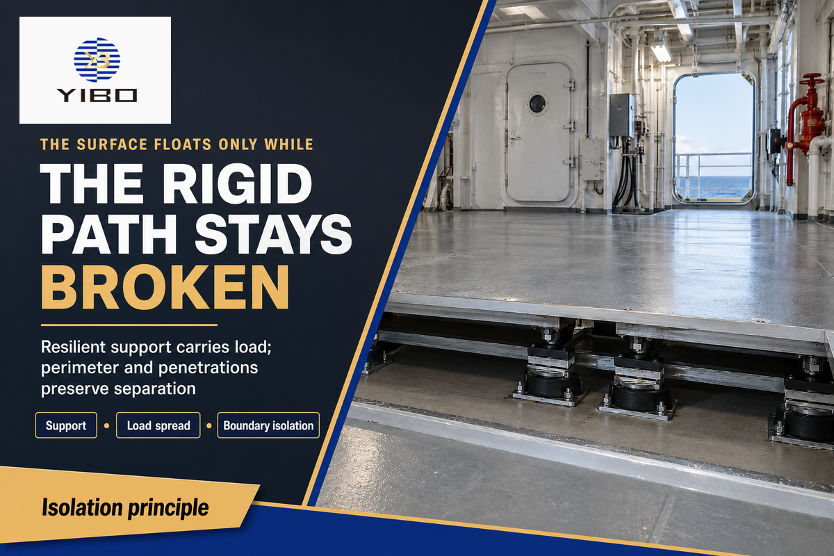
A floating assembly “floats” because its loaded upper surface has no unintended rigid path to the structural deck or surrounding construction. The resilient support carries the design load while permitting controlled relative movement, and the load-distribution layer spreads local forces without crushing, bypassing, or puncturing that support.
Beginning at the bottom, a stack typically includes a released steel deck, resilient insulation, load-spreading board/plate/compound and finish as specified. Acoustic boundary is completed with perimeter isolation and isolation of columns, pipes, cables, drains, doors, and furniture. The finish may be carpet, vinyl flooring, or another approved surface, but it does not create the isolation on its own.
| Part | Primary duty | Interface question |
|---|---|---|
| Structural deck | Base structure and excitation path | Is the deck released, clean, dry, and within the approved preparation condition? |
| Resilient layer | Elastic separation | Is support continuous and matched to the load case? |
| Load-distribution layer | Spreads concentrated and walking loads | Do joints, edges, and fixings preserve isolation? |
| Topping or compound | Levels or completes the load surface where specified | Is it part of the documented build-up and application sequence? |
| Finish and adhesive | Wear, cleaning, appearance, and room use | Are finish and adhesive inside the required fire and service scope? |
| Perimeter and penetrations | Stops rigid bypass paths | What moves, what touches, and what is hidden next? |
This one-dimensional mass-and-spring sketch provides an approximate explanation of the principle, but its detail is not sufficient for reliable low-frequency prediction. A ship-cabin mock-up study in Applied Acoustics found that below 100 – 200 Hz deck plate elasticity is important. The warning is relevant: treating a flexible deck plate as rigid in a calculation is likely to misrepresent the challenging low-frequency range in a project.
Evidence capsule. In the 2008 ship-cabin study, deck-plate elasticity affected prediction below about 100–200 Hz. That result explains a modeling boundary; it does not provide a universal product rating, minimum thickness, or guaranteed onboard reduction.
Freeze the Design Inputs Before Choosing a Build-Up
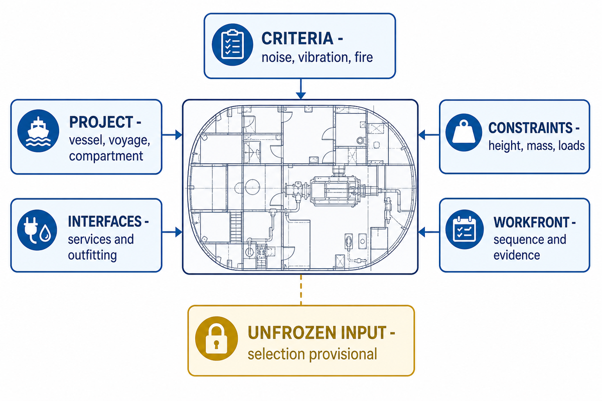
The shipyard should select the build-up only after freezing the compartment, excitation, acceptance criteria, fire division, available height, mass allowance, loads, interfaces, and required evidence. Should any one of these elements remain undefined, the selection will also be considered provisional, and all affected details on the drawing will remain unfinished.
First consider the occupied space and the source next to, above, or below it; the source may be machinery, another space, or non-machine excitation. The requirements for a passenger cabin may differ greatly from those for an office installation. However, both may use the same general flooring label even though their design questions differ. Note the voyage and operating conditions because onboard noise and vibration requirements may depend on vessel type, space, and the complete measurement condition.
| Input | Why it matters | Owner | Freeze evidence |
|---|---|---|---|
| Vessel and voyage profile | Defines the regulatory and measurement context | Owner or designer | Design basis |
| Compartment and occupancy | Identifies the protected use and schedule | General arrangement lead | Room list and grid |
| Excitation and adjacent source | Frames direct and flanking paths | Acoustic specialist | Source-path-receiver note |
| Noise criterion | Sets the onboard acceptance question | Owner and class team | Approved criterion register |
| Vibration criterion | Keeps motion separate from sound-pressure evidence | Owner and vibration specialist | Measurement plan |
| Fire division and approval route | Defines required fire evidence objects | Fire and class lead | Fire-control plan and submittal list |
| Height and mass allowance | Controls doors, thresholds, outfitting, and weight | Naval architect | Weight and space reservation |
| Distributed and point loads | Controls support and load-spreader design | Structural and outfitting teams | Load schedule |
| Deck condition | Affects release, leveling, and application | Hull and flooring trades | Survey and release record |
| Moisture and service exposure | Shapes finish, protection, and repair controls | Room owner | Exposure schedule |
| Penetrations and drains | Potentially bypass resilient separation | System trades | Coordinated penetration drawing |
| Thresholds and partitions | Set edge and flanking conditions | Outfitting lead | Interface details |
| Equipment and furniture | Introduces anchors and point loads | Equipment owner | Foundation and fixing schedule |
| Workfront sequence | Determines access to hidden hold points | Production planning | Integrated look-ahead plan |
| Evidence deliverables | Prevents a late certificate and test mismatch | Quality lead | Submittal and handover index |
Separate fire, airborne noise, impact excitation, and vibration. According to the US Coast Guard structural fire-protection guidance, acoustic and thermal insulation must comply with fire safety; however, US regulation doesn’t impose comfort-acoustic performance on them. Therefore, a fire safety rating doesn’t imply a certain level of sound reduction, and an acoustic report doesn’t imply a Class A fire result.
Procurement objection: “We need a price before every input is final.” Request a budget indication against a provisional schedule with clear height, mass, fire, load and interface assumptions frozen prior to the grant of technical approval.
How the Layers Share Load, Isolation, and Surface Duties
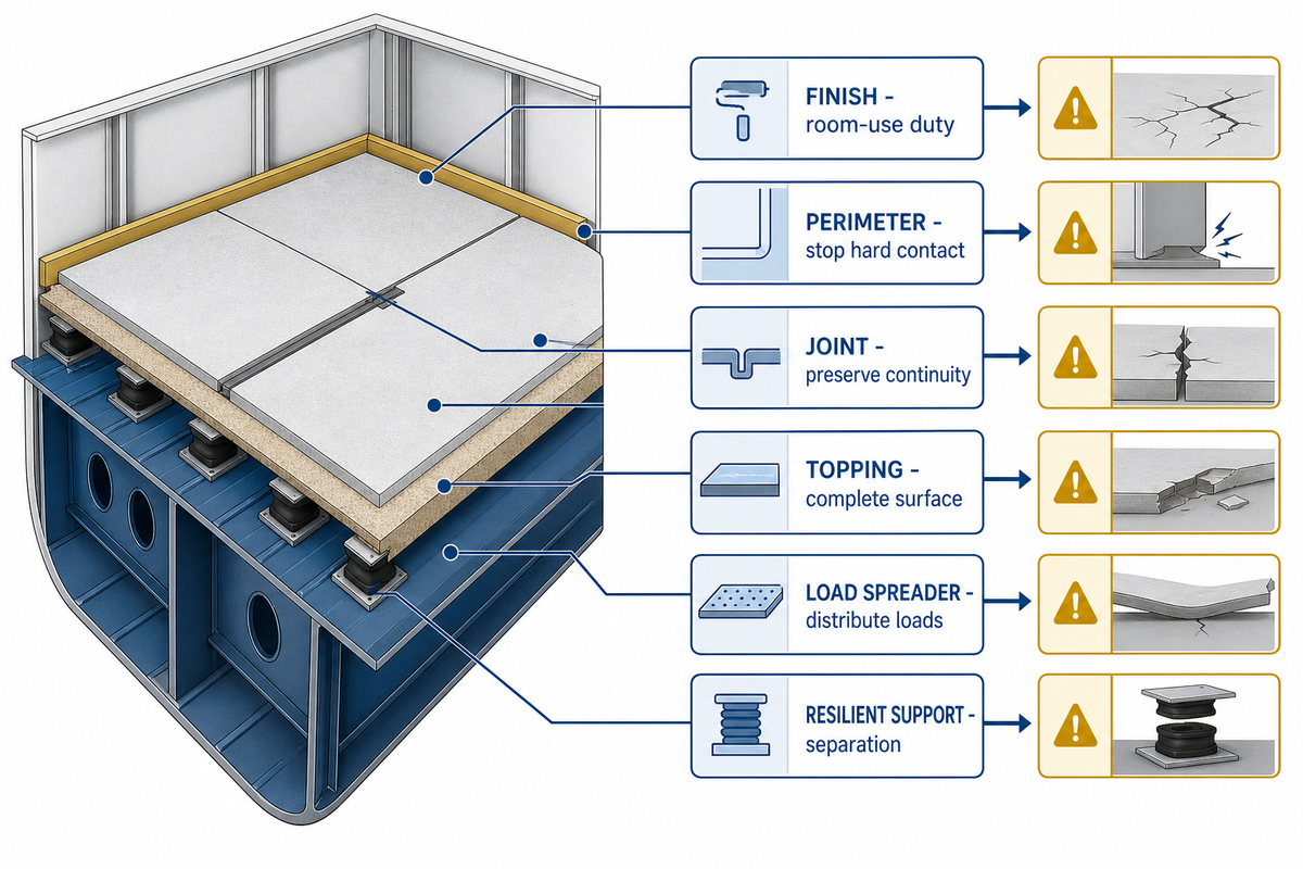
Each distinct layer has a designated task: resilient materials separate vibration paths, an upper layer distributes load, optional compounds establish the required surface, and the finish meets the room-use needs. A substitute material could change the behavior of load, acoustic, fire, application and interface, even if the replacement seems similar.
Review substitutions by function and evidence, not by material name. Mineral wool, a board, an adhesive, or a finish cannot inherit a tested assembly’s performance merely because each belongs to the same generic family. Likewise, “marine-grade,” “waterproof,” “non-slip,” or “easy to clean” don’t indicate performance of the floating-floor duty.
| Element | Credible failure | Observable consequence | Document to check |
|---|---|---|---|
| Resilient support | Compression, gap, tear, wetting, or overload | Uneven support or changed isolation | Approved build-up and load basis |
| Load spreader | Weak joint or local deflection | Cracking, rocking, or concentrated load transfer | Joint layout and structural note |
| Topping or compound | Wrong condition, mix, cure, or bond | Surface defect or incomplete load path | Current application instruction and batch record |
| Joint and seam | Opening, hard packing, or misalignment | Local weakness or bridge | Joint detail and inspection record |
| Perimeter strip | Missing, cut early, or filled rigidly | Edge contact and flanking path | Room-edge detail and witness photo |
| Finish and adhesive | Wrong scope, cure, or surface preparation | Finish failure or evidence mismatch | Finish approval and supplier instruction |
Fire evidence is considered object-specific. The applicable file may concern the primary deck covering, surface floor covering, adhesive, structural insulation, or tested deck construction. According to the Coast Guard structural fire-protection guidance (https://www.dco.uscg.mil/CG-ENG-4/SFP/), accommodations systems aren’t type approved as single objects under their program. Fire protection elements are addressed in their respective groups.
“The various structural fire protection elements (bulkhead panels, ceiling, insulation, etc.) of which the system is constructed are approved separately under their individual approval categories.”
Consider an umbrella statement such as “IMO approved” as a prompt to examine the actual certificate and the scope. Don’t consider this the completion of your review.
Procurement objection: “The proposed substitute looks identical.” Similar in appearance isn’t a basis for determination of equal dynamic stiffness, load behavior, usage, or approval scope. An equivalence review for each affected duty is required for all of these.
Run the Marine Floating Floor Bridge Hunt Before Cover-Up
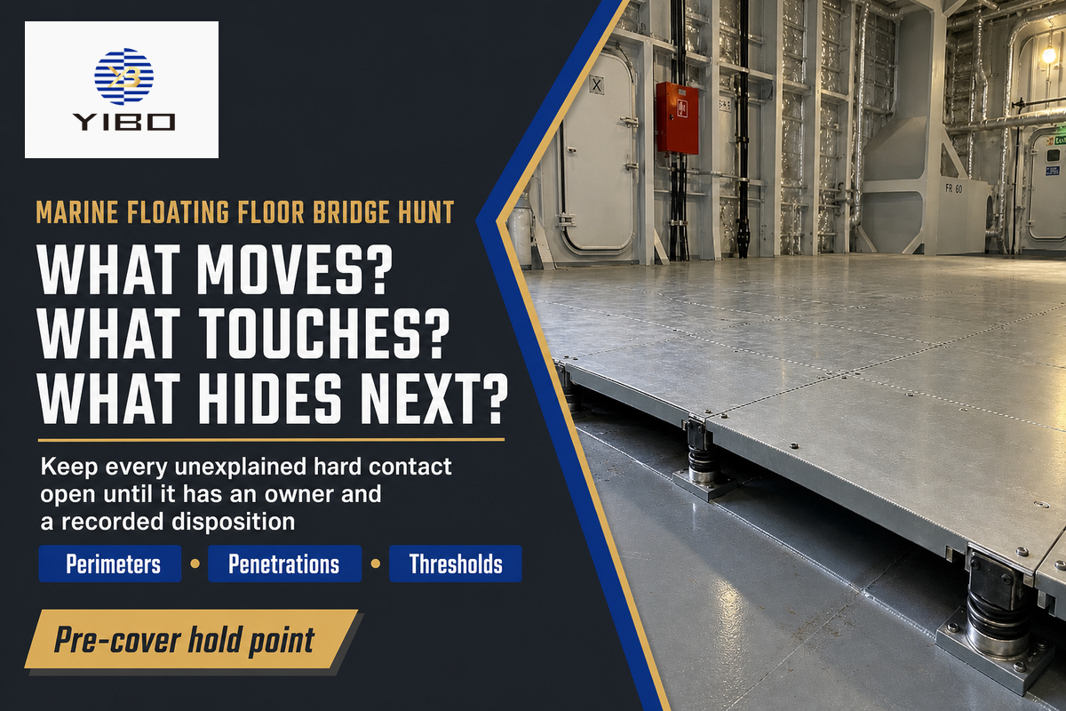
The marine floating floor Bridge Hunt is a pre-cover inspection that challenges every interface to identify a concealed rigid bypass path. That turns the preceding layer-role review into an interface inspection: each layer can perform only if its boundaries stay decoupled (https://pmc.ncbi.nlm.nih.gov/articles/PMC13363800/).
For each boundary, ask three questions: What’s intended to move? What’s in contact with it now? What will the next trade conceal? Any unexplained hard contact remains open work until the responsible designer or trade records a disposition and the witness point is released.
The method transforms the general “check isolation” instruction into a conversation in the workfront. A cable tray support can sit within electrical outfitting, a door saddle within joinery, and a pipe sleeve within piping. However, each of these can reconnect the loaded surface to the steel deck or bulkhead. The flooring crew can’t close those interfaces on their own; the worksheet assigns an owner before access is lost.
| Interface type | Observed contact | Responsible trade | Disposition and witness |
|---|---|---|---|
| Perimeter | Mortar, board, debris, or finish at bulkhead | Flooring / lining | Photo, grid, corrective record |
| Door threshold | Rigid saddle or fixing across isolation | Joinery / flooring | Approved threshold detail |
| Pipe sleeve | Pipe, collar, or seal bearing on floor edge | Piping | Sleeve-detail witness |
| Cable route | Support or bundled cable crossing the break | Electrical | Support-path confirmation |
| Column or pillar | Board, compound, or trim in hard contact | Flooring / outfitting | 360-degree photo set |
| Drain | Body, flange, or repair tied to both structures | Piping / wet-area lead | Approved drain interface |
| Equipment base | Fastener or packer passing through the floor | Equipment owner | Load and fixing review |
| Partition track | Track fixes or lining reconnecting deck and floor | Partitions | Partition-interface release |
| Temporary works | Screws, shims, blocks, offcuts, or protection debris | Installing trade | Removal confirmation |
While end-stage measurements are important, they’re no substitute for seeing the interface when it’s accessible. A failed onboard result may indicate that something isn’t right, but may not identify which concealed threshold, screw, support, or perimeter caused it. The Bridge Hunt preserves the location, owner, drawing revision, and repair decision of the defect before the physical evidence is lost.
Procurement objection: “Inspection time will delay cover-up.” Tie the witness points to the production look-ahead and group them by compartment. A short, scheduled pre-cover release is more controllable than opening finished work to locate an undocumented contact.
Install in a Sequence That Protects Decoupling
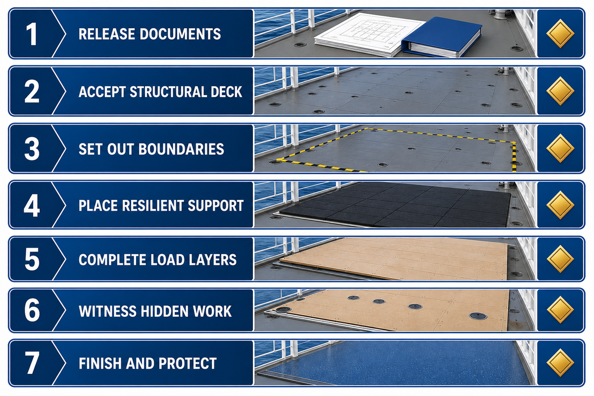
The installation sequence has to protect resilient separation from deck release until the finish is handed over. Documents, deck readiness, setting-out, boundary isolation, layer placement, interface completion, hidden-work release, and surface protection require explicit hold points rather than one final completion check.
- Release approved documents — issue the current build-up, interface details, material instructions, inspection plan, and compartment schedule to the workfront.
- Accept the structural deck — record grid, condition, cleanliness, moisture condition where relevant, and the disposition of welds or irregularities.
- Set out boundaries — mark perimeters, penetrations, thresholds, partitions, drains, and equipment bases before materials hide the deck.
- Place resilient support — protect continuity, joint arrangement, material identity, and the approved load path.
- Complete load layers and interfaces — follow the documented joint, compound, adhesive, application, and protection sequence without creating hard contact.
- Witness hidden work — close each Bridge Hunt item, attach location-bound photographs, and release the compartment before concealment.
- Finish and protect — complete the specified surface, control access and later trades, and carry open deviations into the handover record.
Record material identity and application conditions when the supplier instructions require them. Include batch references, drawing revisions, work dates, environmental or product conditions, the identity of the installer, and the status of the protection system. Do not invent universal values for cure time, mix ratio, layer thickness, or deck tolerance. The approved system (https://www.dco.uscg.mil/CG-ENG-4/SFP/) and the supplier instructions will determine these values.
Do
- Verify the current drawing at the compartment.
- Assign every interface to a named trade.
- Remove temporary fixings and debris before release.
- Protect completed areas from follow-on work.
Don’t
- Accept a generic “installed” tick box.
- Fill an unexplained gap with rigid material.
- Cover a deviation without written disposition.
- Assume a later test can locate every hidden defect.
Safety controls cover handling, mixing, personal protection, ventilation, curing, and re-entry. They’ll be derived from approved vessel documents, safety data, supplier instructions, and the permit system at the work site. No safety measures found on a blog will be a substitute for them.
Procurement objection: “The product is advertised as easy to install.” The ease of application doesn’t eliminate the requirement of interface coordination, witness, safety, or evidence. The controls for the workfront need to be priced along with the supplied materials.
Witness Hidden Interfaces Before the Next Trade Covers Them

A hidden-work release must specify the location of the work, the revision of the drawing that governs the work, the observations, the identity of the installer and witness, and how each deviation was closed. Those records turn the previous section’s workfront hold points into traceable evidence. Without a compartment, grid, date, revision, and disposition, a photograph is an illustration rather than a traceable acceptance record.
The following fields form the minimum record structure: vessel or hull number; deck, compartment, and grid; drawing revision; date and time; installer; material or batch identity where applicable; released deck condition; perimeter continuity; penetration and threshold status; joint and seam condition; removal of temporary aids; debris check; photograph references; open nonconformities; repair or concession reference; and release signature.
Pre-cover witnessing and final testing answer different questions. The witness record demonstrates that accessible work matched the released detail at a known time. Post-installation noise or vibration measurements assess stated conditions and acceptance uses. The ISO 2923:1996 overview says onboard noise measurements can support acceptance comparisons, monitoring, vessel comparison, further investigation, and alarm-audibility assessment. It does not state that a single measurement can identify all construction defects.
Procurement objection: “We already take many photographs.” Quantity isn’t traceability. Make the file name or record ID resolve to the exact location, revision, witness, and disposition.
Evidence capsule. ISO 2923:1996 was confirmed in 2022 and remains published. Its stated uses include acceptance, monitoring, comparison, and investigation; none turns an onboard sound reading into a complete map of concealed floor interfaces.
Use the Lab-to-Onboard Evidence Translator
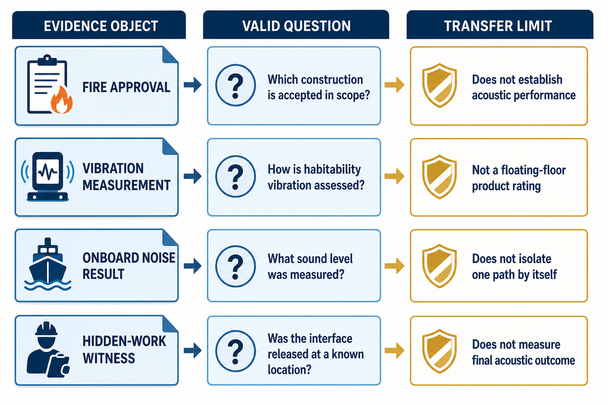
The Lab-to-Onboard Evidence Translator matches each document to the exact question, configuration, metric, setting, and limit it can support. This takes the location-bound witness record from the prior section and tests what each document can actually prove.
Evidence is transferable only when its specimen, boundaries, metric, frequency range, operating condition, revision, and approval scope match the project question closely enough. A larger isolated number isn’t automatically better evidence; relevance depends on what was measured, where, how, and for what purpose.
| Evidence object | Valid question | Transfer limit | Missing input to request |
|---|---|---|---|
| Assembly laboratory acoustic report | What did the stated specimen achieve under the method? | Different deck, boundary, load, or frequency context | Full build-up, method, metric, spectrum, substrate |
| Component data sheet | What material properties and application limits are declared? | Does not rate the complete installed assembly | Revision and approved system relationship |
| Fire type-approval certificate | Which product or construction is accepted within stated scope? | Does not establish acoustic performance | Certificate holder, configuration, limits, validity |
| FTP test report | How did the specimen perform in the cited fire test? | Orientation, substrate, finish, and specimen scope | Test part, drawings, conditioning, result |
| ISO 20283-5 vibration measurement | How is habitability vibration assessed in its stated vessel scope? | Not a floating-floor product rating | Vessel, voyage, occupied space, range, condition |
| ISO 2923 onboard noise result | What sound level was measured under stated conditions? | Does not isolate one transmission path by itself | Operating condition, location, instrument, criterion |
| Hidden-work witness record | Was the interface accessible and released at a known location? | Does not measure final acoustic outcome | Grid, revision, witness, photos, disposition |
| Supplier declaration | What does the named supplier declare? | Authority and verification depend on the document | Issuer, basis, product, revision, linked evidence |
| Onboard troubleshooting check | Which hypothesized path changes under a bounded test? | Local result may not generalize to every room | Hypothesis, variable, baseline, repeat condition |
The official ISO 20283-5:2016 scope covers habitability-related vibration measurement, evaluation, and reporting for passenger and merchant ships in the 1–80 Hz range, with stated vessel, voyage, and occupied-space conditions. It can serve as a basis for addressing an onboard vibration question, although it is not a floor product certificate. ISO 2923 addresses onboard noise measurement and its uses. Keep the two measurement queries distinct.
The IMO Code on Noise Levels on Board Ships, Resolution MSC.337(91), has its own provisions pertaining to the application of the requirements, including vessel type and gross tonnage, as well as certain exclusions. Be certain the vessel under consideration is within the scope of the requirements prior to quoting the requirements. A citation of a given number in a submission doesn’t verify that the proposed project, space, operational condition, and acceptance criterion have been satisfied.
Procurement objection: “One report shows a higher decibel result.” Please provide the metric, spectrum, specimen, substrate, boundary condition, uncertainty, and intended use. Two numbers with different definitions shouldn’t be ranked as if they measure the same thing.
Evidence capsule. ISO 20283-5:2016 states a 1–80 Hz vibration range and defined habitability scope. ISO 2923:1996 addresses onboard noise measurement. Neither standard is, by itself, a laboratory acoustic rating for a marine floor build-up.
Troubleshoot Underperformance by Transmission Path
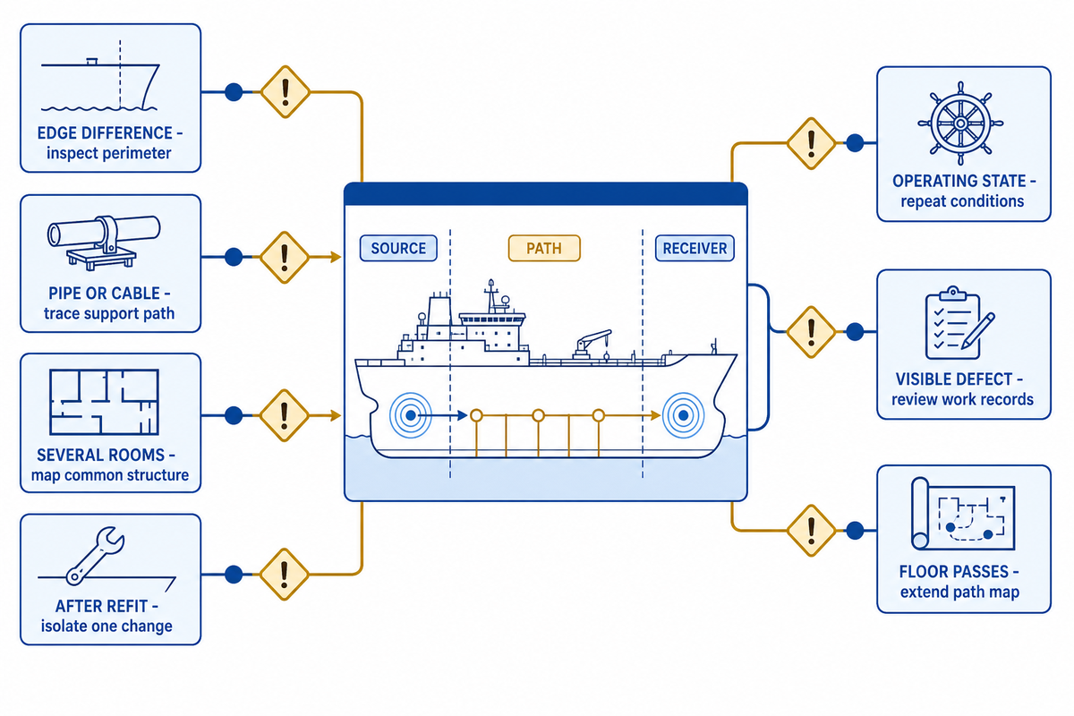
When measured or perceived performance is weak, divide the problem into direct transmission, rigid bridging, structural flanking, damaged or incorrect work, test-condition effects, and later alterations. Once the evidence limits are clear, an engineering review can compare transmission paths without treating unlike tests as interchangeable. Test the hypothesis that best separates those paths before replacing broad areas of otherwise unproven flooring.
Begin with the source-path-receiver map and compare affected with unaffected compartments. Review the operating state, measurement location, and background conditions (https://wwwcdn.imo.org/localresources/en/KnowledgeCentre/IndexofIMOResolutions/MSCResolutions/MSC.337(91).pdf), drawings, bridge-witness records, repair history, and later penetrations. Then change one bounded variable or inspect one discriminating interface. Opening everything at once destroys the evidence that could distinguish a threshold bridge from a hull-borne flanking route.
| Symptom | Plausible path | Discriminating check | Bounded next action |
|---|---|---|---|
| One edge reads or feels different | Perimeter bridge | Compare edge and center; inspect edge record | Open only the suspect edge detail |
| Issue follows a pipe or cable route | Penetration or support bypass | Trace support path and coordinated detail | Correct the identified interface |
| Several rooms share the issue | Common structure or source condition | Map rooms against framing and source state | Test one representative path |
| Change appeared after refit | New anchor, partition, threshold, or service | Compare alteration drawings and before/after records | Reverse or isolate one change |
| Result shifts with operating state | Source or test-condition effect | Repeat under controlled matching conditions | Correct the comparison basis |
| Local surface defect is visible | Workmanship, loading, moisture, or protection | Review batch, application, load, and exposure records | Repair to approved instruction |
| Floor check passes but room result does not | Wall, ceiling, duct, door, or hull flanking | Extend the path map beyond the floor | Investigate the dominant adjacent path |
The troubleshooting goal isn’t to defend the floor or to blame another trade. It’s to locate the dominant path with the least destructive test. Record the baseline, the one variable changed, the repeated condition, and the result. If the result doesn’t separate the hypotheses, return to the path map instead of immediately escalating to a full replacement.
“Replacement is faster than investigation.” This is likely the case only when the floor itself is already proven to be the dominant path. Replacing it won’t correct a bulkhead, duct, threshold, or later anchor that carries the same excitation around the new work.
Protect Isolation During Maintenance and Refit
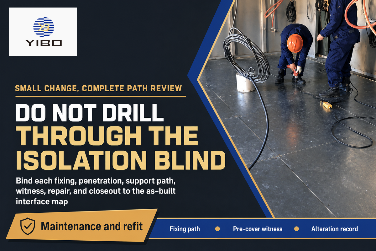
An assembly remains floating if subsequent work maintains separation. Furniture anchors, pipe supports, cable trays, partitions, thresholds, drains, wet-area repairs, and new equipment all must undergo change control prior to drilling, fastening, packing, or rebuilding an interface.
For each alteration, record the proposed fixing or penetration, its load and support path, the approved interface detail, a pre-cover witness point, the repair instruction, photographs, and the closeout reference. A durable outcome depends on an as-built interface map, not a floor-plan color that merely says “floating floor.” The map should show intended isolation breaks and locations where drilling is restricted pending review.
A paper found in the National Maritime Research Institute of Japan’s repository studied the vibration-isolation effect of the rockwool floating floor in one of the classrooms of the TAISEIMARU training ship. According to the abstract, the floor’s vibration-isolation ability after 10 years was no lower than at construction. That’s specific performance for a certain area and isn’t a generalized service life assurance. This guide also doesn’t adopt the paper’s much longer extrapolation. Changes in the environment such as water incursion, hard repairs, changes in loads or penetrations can result in different conditions.
Procurement objection: “The refit item is small.” A small fastener may cross the resilient break. Route minor changes through the interface map when they touch the floor, perimeter, penetration, or supported equipment.
Evidence capsule. The TAISEIMARU paper reports that one classroom floor retained vibration-isolation ability no lower than its construction-time value after 10 years. It does not establish a blanket lifespan for other materials, ships, loads, or exposure histories.
Build the Handover and RFQ Evidence Schedule
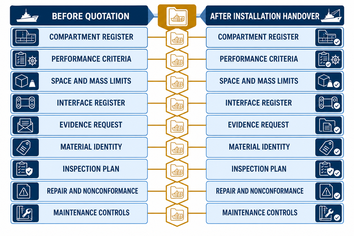
A good request for quotation and handover pack uses the same evidence index. The map used to control later refit changes now becomes the index for procurement and closeout. Before quotation, this index shows compartment, criteria, loads, space restrictions, interfaces, finish, exposure, and required documentation. After installation, this index binds approved submittals, material identity, witnesses, deviations, repairs, and as-built records to those inputs.
| Schedule item | Before quotation | Retained after installation |
|---|---|---|
| Compartment and deck register | Area, grid, occupancy, sequence | As-built location index |
| Performance criteria | Noise, vibration, fire, load, finish | Accepted criteria and test reports |
| Space and mass limits | Available height and weight allowance | Approved and as-built build-up |
| Interface register | Perimeters, thresholds, services, equipment | Closed Bridge Hunt worksheet |
| Evidence request | Exact acoustic and fire document questions | Accepted revisions and scope review |
| Material identity | Proposed products and document revisions | Delivery, batch, and substitution record |
| Inspection plan | Hold points, witnesses, acceptance fields | Signed releases and photograph index |
| Nonconformance and repair | Proposed control route | Disposition, repair, and reinspection |
| Maintenance controls | Protected interfaces and future access | As-built map and alteration procedure |
Teams interested in a separate commercial discussion based on available product constructions and submittals can refer to Yibo’s marine floating floor systems; Yibo reports cooperative relationships with Guangzhou Shipyard International and CSSC Huangpu Wenchong Shipbuilding. Keep the discussion related to the project schedule above so the supplier can identify missing data when evaluating the proposal as final, while keeping adjacent Yibo scopes separate: primary deck covering, self-levelling deck covering, marine PU floor, and passenger-vessel applications; Yibo’s first-party range statement also lists high-sound-insulation floating floors, damping coatings, ordinary deck coverings, PU leveling coverings, and imitation-teak floors, but these company-supplied statements do not prove a current contract, class approval for a named build-up, or project-specific acoustic performance.
Key takeaway
One location-bound schedule should connect design inputs, interface decisions, hidden-work witnesses, test evidence, repairs, and future alterations. A certificate folder without that chain cannot explain what was installed in a particular compartment.
Ready to make the enquiry traceable?
Share compartment, height, mass, load, fire, acoustic, threshold, penetration, and equipment-interface inputs, then request a project-specific document index and responsibility boundary; as first-party company context, Yibo states that Suzhou Yibo Industry & Trade Co Ltd was founded in September 2001 in Huangqiao Street, Xiangcheng District, Suzhou, operates on a site of more than 6000 m², and maintains an ISO 9001:2015-certified quality-management system.
Frequently Asked Questions About Marine Floating Floors
What are the downsides of a floating floor?
Answer
A marine floating floor adds height, weight, interface coordination, and inspection duties. The handover schedule above shows why those duties continue beyond installation. Its acoustic benefit can be weakened by a small rigid bridge at a perimeter, threshold, penetration, or equipment support, and many defects become hidden after covering. Repairs and later refits also need change control. These are assembly-level risks, not the usual disadvantages of household click flooring. Judge them against the approved acoustic, fire, load, space, and maintenance requirements.
How does the floating floor work?
Answer
The load-bearing surface is separated from the structural deck by a resilient layer, creating an isolated mass-and-resilience arrangement. That separation reduces transferred vibration and sound energy while the upper layer distributes loads. The mechanism depends on the complete build-up and its boundaries. If a rigid fixing, threshold, pipe, wall edge, or debris path bypasses the resilient layer, energy can flank the intended isolation. Performance can’t be assigned from one material alone.
What should be inspected before a marine floating floor is covered?
Answer
Inspect the released deck, layout, resilient-layer continuity, perimeter strips, seams, joints, penetrations, thresholds, columns, and equipment interfaces. Confirm that temporary fixings, offcuts, and debris can’t create rigid contact. Record the compartment or grid, drawing revision, material identity, date, responsible trade, photographs, and the disposition of every deviation before the next layer hides it.
Is an A-60 floating floor automatically the best acoustic option?
Answer
No. A-60 addresses a defined fire-resistance classification and evidence scope; it doesn’t rank acoustic performance. Compare the project’s sound and vibration criteria against a relevant build-up, substrate, boundary, method, and metric, then verify the fire documents separately.
Can a finished onboard sound test identify every installation defect?
Answer
No. An onboard result can confirm or challenge a target under the stated operating and measurement conditions, but a room-level result often combines direct transmission, flanking, source behavior, background, and later alterations. It may show that investigation is needed without locating a hidden screw, threshold bridge, pipe support, or perimeter contact. Use the result with coordinated drawings, compartment-bound witness records, alteration history, and controlled troubleshooting checks. Compare like conditions, form a transmission-path hypothesis, change one bounded variable, and repeat. Opening or replacing the whole floor first can destroy useful evidence while leaving a wall, duct, or structural flanking path untouched.
What should a shipyard include in a marine floating floor RFQ?
Answer
Include the vessel and compartment schedule, occupancy, adjacent sources, criteria, fire division, height and mass limits, distributed and point loads, deck condition, finish and exposure, plus coordinated thresholds, penetrations, partitions, drains, and equipment bases. Request the proposed build-up, scope-matched evidence, drawings, application documents, witness points, material records, repair route, and as-built handover index.
Control the Interfaces, Then Preserve the Evidence
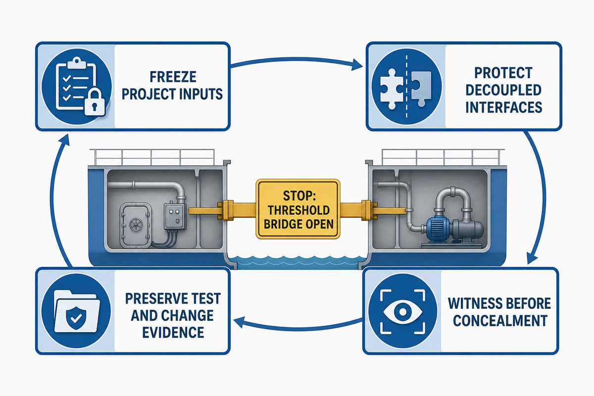
A marine floating floor is a controlled chain of events and not a material label. For example, during production a threshold found bridging at a pre-cover witness creates a rework risk, so it should remain open until its approved repair and location-bound closeout are recorded. Protect the installation sequence, freeze project inputs and coordination boundaries, witness interfaces before concealment, interpret every document in scope, troubleshoot weak performance by transmission path, and control later changes.
When these records share the same compartment and drawing references, the owner receives more than a surface. The handover pack tells what was intended, what was installed, what was witnessed, which deviations were closed, how results were interpreted, and where future work must pause for review.
References & Sources
- Insertion loss prediction of floating floors used in ship cabins Applied Acoustics, 2008.
- Structural Fire Protection approval guidance United States Coast Guard.
- ISO 2923:1996, Acoustics, Measurement of noise on board vessels International Organization for Standardization.
- ISO 20283-5:2016, Measurement, evaluation and reporting of vibration with regard to habitability International Organization for Standardization.
- Resolution MSC.337(91), Code on Noise Levels on Board Ships International Maritime Organization.
- Ten-year floating-floor vibration investigation aboard TAISEIMARU National Maritime Research Institute, Japan.
Commercial marine flooring systems
Plan the deck build-up before the workfront is released.
Yibo manufactures commercial marine flooring systems in Suzhou for vessel projects that need a coordinated deck-covering, resin-floor, or acoustic-floating-floor build-up.
Review marine deck covering systems, marine resin floor systems, and marine acoustic floor systems against the vessel area and planned application sequence.
Project enquiry
Give the engineering team the inputs that shape the system review.
Include the vessel area, substrate or deck condition, intended floor build-up, fire or acoustic target, and project schedule so the enquiry can begin with the relevant deck constraints.
Send Your Deck Schedule


![Marine PU Floor: Selection & Installation [Guide]](https://yibomarine.com/wp-content/uploads/2026/09/marine-pu-floor-blog-featured-150x150.png)