
Get in touch with Yibo Company


Updated September 2026
Self leveling marine screed is a flowable underlay route used to create a generally flat receiving surface within a bounded deck zone. Trowel-applied underlays are shaped deliberately around falls, penetrations, and controlled transitions; cement-system labour remains product- and workfront-specific. Neither label proves that a product fits the thickness, substrate, finish, fire-test route, or release schedule of a particular vessel.
The first comparison step is to define the surface each zone must become and the workfront available to create it. Product data and project evidence then support or rule out each route. This article focuses on route selection; detailed mixing, placement, curing, and handover procedures remain in the separate application guide.
Self leveling marine screed suits broad flat fields when the named product, layer build-up, access, and evidence route permit flow placement. Trowel-applied underlay gives the installer deliberate shape control at falls and transitions. Select by deck-zone geometry first, then verify every product-specific limit.
Decision brief
- Density alone can’t identify the right placement route.
- A self-levelling label doesn’t promise a universal thickness, slope, or cure time.
- Falls, drains, thresholds, and small transitions need explicit shape-control decisions.
- Approval evidence must match the named product and complete proposed build-up.
- Unresolved structure, movement, access, or interface inputs justify postponing both routes.
Self-Levelling and Trowel-Applied Underlay at a Glance
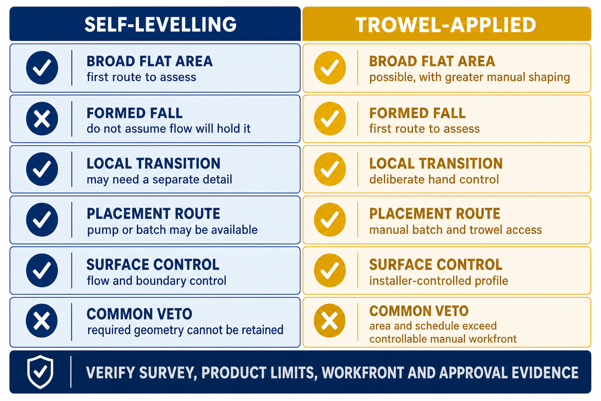
A self-leveling route uses flowable material that spreads across a bounded area, while a trowel-applied route relies more on manual shaping and placement. The routes differ in labour, access requirements, edge control, and the intentional geometry an installer can form. It doesn’t negate the need to check the chosen product and the complete construction of the deck. The ASTM C1708/C1708M flow-test framework also separates initial flow, retained flow, and healing-time observations, so one “self-leveling” label cannot settle the project comparison.
Self-levelling route
- First candidate for a broad, generally flat field
- May support pump or continuous-batch logistics
- Needs defined boundaries, penetrations, and flow control
- Still governed by named-product thickness and interface limits
Trowel-applied route
- First candidate for deliberate falls and local shaping
- May suit divided, penetrated, or restricted work zones
- Depends on crew access and controlled hand placement
- Still governed by named-product layer and finish requirements
| Criterion | Self-levelling route | Trowel-applied route | Evidence still needed |
|---|---|---|---|
| Broad flat area | Often the first route to assess | Possible, with greater manual shaping | Survey, tolerance, product limits |
| Formed fall | Do not assume flow will hold it | Often the first route to assess | Fall drawing, drain detail, approval |
| Local transition | May need a separate detail | Allows deliberate hand control | Edge, minimum thickness, finish interface |
| Placement route | Pump or batch placement may be available | Manual batch and trowel access dominate | Current product instructions, workfront plan |
| Surface control | Flow and boundary control | Installer-controlled profile | Required finish and next-layer condition |
| Common veto | Required geometry cannot be retained | Area and schedule exceed controllable manual workfront | Trial, method statement, responsible approval |
What Each Method Actually Controls
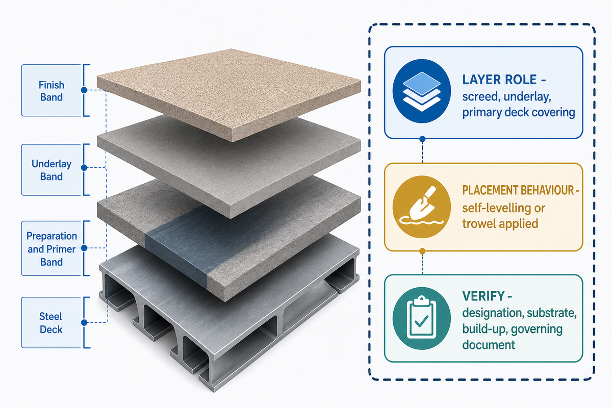
Behavioural placement terms such as “self-levelling” and “trowel applied” describe placement techniques, but not complete material specifications, finish floor level promises, or approval categories. “Screed,” “underlay,” and “primary deck covering” can describe different layer functions across drawings and suppliers, so the enquiry needs the intended function. Therefore, the function must be specified in the inquiry, including briefs that use the phrase “self leveling underlayment.” The Coast Guard guidance separates primary deck coverings from floor finishes.
A description of a route becomes meaningful when combined with a designation, substrate, primer or bonding arrangement, thickness strategy, final covering, service environment, and governing document. A patent assigned to Illinois Tool Works Inc (WO2011014342A1) describes local trowel smoothing within one self-leveling underlayment method. This example shows that the two terms aren’t absolute opposites; however, it doesn’t show that every self-leveling underlayment forms falls, nor does it provide evidence of Yibo technology, licensing, or adoption. The United States Coast Guard finish-material guidance is a useful scope check because it distinguishes primary deck coverings from exposed floor finishes.
Are screed and self-levelling the same?
No. Screed is a broad construction term for a layer used to create or adjust a surface. Self-leveling definitions describe the placement and flow behavior claimed for particular named formulations. Trowel-applied materials can also be used as underlays. Instead of using the words interchangeably, define the layer by its function, product designation, substrate, geometry, finish, interfaces, and approval evidence.
Yibo’s published product taxonomy separates self-levelling and non-self-levelling screed underlays which is a distinction made in a first-party catalogue or system. This is a first-party catalogue distinction and leaves universal classification and the same range of applicability unproven.
Flat, Fall or Feather? The Flat–Fall–Feather Screed Route
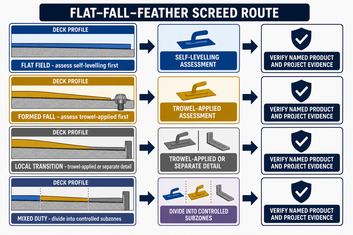
The Flat–Fall–Feather Screed Route classifies each deck zone as a flat field, formed fall, or local transition. This is an editorial method, not a rule or a product standard of the International Maritime Organization. It presents a shortlist that final product limits and project evidence must still validate.
1Mark flat fields
Map the bounded area, finished datum, measured high and low points, penetrations, and required surface tolerance.
2Mark formed falls
Identify intended water routes, drain elevations, start and end levels, thresholds, and the party approving the geometry.
3Isolate transitions
Tag local edges, door clearances, equipment bases, movement details, and any thin or deep locations for separate review.
| Geometry type | First route to assess | Input to record | Limitation or veto |
|---|---|---|---|
| Open flat cabin field | Self-levelling | Area and surveyed min/typical/max in mm | Product range or access does not fit |
| Drain fall | Trowel-applied | Start level, drain level, route | Drain or finish detail unresolved |
| Threshold transition | Trowel-applied or separate detail | Clearance and edge geometry | Minimum edge condition unverified |
| Wide uneven field | Self-levelling with zone review | Point map and outliers | Deep or thin points exceed named build-up |
| Dense pipe penetrations | Trowel-applied | Collars, spacing, work boundary | Interfaces or trade ownership open |
| Mixed flat and fall zone | Divide into controlled subzones | Break line and interface detail | One-route assumption hides two duties |
| Local weld correction | Project-specific local detail | Height, extent, substrate condition | Structural or preparation issue unresolved |
| Unknown geometry | Postpone both | Datum survey and approved finish intent | No defensible route selection yet |
“Level deck” doesn’t mean level for the purposes of classification if there are drains, camber, thresholds, or passenger routes which create local duties. For example, in the UK Maritime and Coastguard Agency’s MSN 1844 M-Amendment 1 MLC 2006 Crew Accommodation Notice, there are sections relating to drainage, scuppers, wet-space floor coverings, and floor to wall junctions. Passenger access and drainage geometry may not be aligned. The design authority should resolve that interface without importing a universal numeric slope or threshold from an unrelated system.
Workfront Access, Mixing and Placement Logistics

The established preferred route may not stand up at the workfront. Consider the location of the batch, route for bags and water, pump location if required, distance of hose or carrying by hand, lift limits, power, ventilation, lighting, washout control, adjacent trades, and the available shift window. Consider those constraints by zone, rather than assuming the vessel offers a single, open, continuous floor.
Self-leveling pumpable products may suit large, open areas when the named product’s placement and mixing sequence can be maintained. If used, a suitable pump system must match the named product and the actual placement route to the zone. Alternatively, a trowel-applied system may be more appropriate for a more confined, divided or penetrated area. These are more planning-related scenarios than a definitive statement. Execution feasibility depends on the named product’s water ratio, mixing equipment, working time, environmental range, edge details, and crew plan.
Please see the Yibo non-self-levelling screed underlay options for a model-specific commercial review. Keep the enquiry neutral by stating the required zone geometry and workfront facts before asking the supplier to nominate a product.
Illustrative Deck Zone A input record: 20 °C, 60% relative humidity, a 30 m material route, a 500 kg lift limit, and an 8 hr shift. Use measured data or controlled project data to replace every value. None is a product limit or recommendation.
Workfront stop point
Don’t select a route while the batch location, material path, water control, ventilation, work-zone boundary, or adjacent-trade release remains unknown.
Thickness, Layer Build-Up and Added Weight
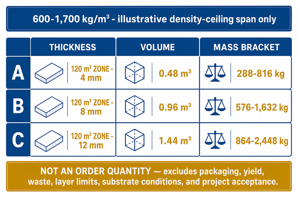
Thickness and density can’t select a route on their own. To begin, procurement needs a zone-by-zone area with measured minimum, typical, and maximum thickness before a self leveling marine screed cost comparison. The supplier then needs to identify the exact model, permitted layer strategy, published density or yield basis, package size, and allowance method before converting geometry into added mass or pack quantity.
4self-levelling models listed
2non-self-levelling models listed
600–1,700kg/m³ published density-ceiling span
The figures above summarize Yibo’s first-party product pages as reviewed in September 2026. The pages don’t show universal limits. The pages publish an 800 kg/m³ density ceiling for one model in each route, AC-J II and YB-4. The models aren’t shown as interchangeable. The comparison shows a density value isn’t sufficient to determine if an underlay is self-levelling or trowel-applied.
Verify the shortlisted route against the current supplier-published Yibo model documents. Request the current technical sheet along with a proposed layer schedule for your measured distribution. The geometric volume isn’t an order quantity until the product-specific fields are finalized.
For illustrative Deck Zone A quantity fields: a 120 m² zone, surveyed at 4–12 mm, also requires the selected model’s kg/m³ or yield basis, kg per pack, layer strategy, and an agreed waste percentage. These values serve as an explanation of the input format, and shouldn’t be mistaken for Yibo product calculations.
Worked geometry check, not an order quantity: For the illustrative 120 m² zone, 4 mm gives 0.48 m³, 8 mm gives 0.96 m³, and 12 mm gives 1.44 m³. Applying the first-party 600–1,700 kg/m³ density-ceiling span only as a theoretical bracket gives 288–816 kg, 576–1,632 kg, and 864–2,448 kg respectively. This excludes packaging, yield, waste, layer limits, substrate conditions, and project acceptance; verify every input against the named product.
Shared Substrate and Interface Preconditions
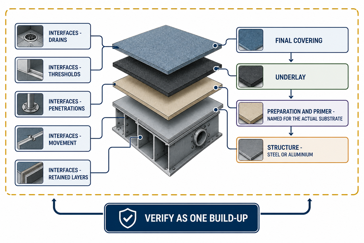
For Deck Zone A, both paths need a defined receiving surface and a specified sequence of layers. Record the type of structure (steel or aluminium) as well as the shop primer or coating, corrosion, contamination, moisture, previous repairs, retained layers, penetrations, drains, thresholds, movement, and final covering. A surface being dry does not, by itself, show that it is prepared. A general cement-based, cementitious, or fibre reinforced label doesn’t establish compatibility with the actual substrates and conditions. State who’s responsible for the structural adequacy and vessel-induced deck movement. Generic product advice may not resolve those engineering judgements.
What should I put down before self-leveling compound?
Use only the primer, if any, specified for the selected product, actual substrate, preparation method, and complete build-up. There is no responsible universal primer recommendation. The project record identifies the steel or retained layer, surface condition, preparation method, primer designation, application window, and any adhesion or trial requirement. Define interfaces and final covering at this step.
Detailed sequencing belongs in the self-levelling application and handover guide. This comparison identifies the shared inputs that must be closed before the execution plan is finalized. Carpet, polyvinyl chloride flooring, and tile each require a named, prepared interface rather than one assumed state of readiness.
Do verify as one build-up
- Exact substrate and surface status
- Preparation and primer identities
- Drain, threshold, penetration, and movement details
- Underlay-to-finish compatibility and evidence
Do not infer from a label
- One primer fits every marine system
- Clean-looking steel is ready for application
- A retained layer is compatible because it is sound
- Underlay approval covers every changed finish
Working Time, Cure Evidence and Floor Release
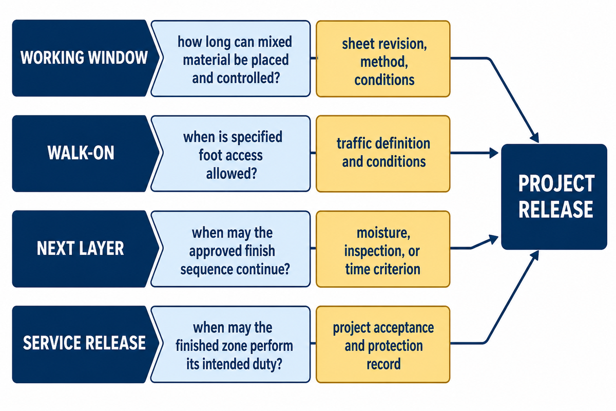
Compare four clocks separately: mixing and working window, readiness for defined foot traffic, readiness for the next layer, final service release. “Fast” products can look slower or faster simply because two offers report different clocks. Attribute every time value to a named product, specified layer, test basis, and stated environment. The ASTM C1708/C1708M test scope treats flow and healing as measured properties; it does not define a vessel’s foot-traffic, overcoat, or service-release milestone.
| Clock | Question it answers | Evidence field | Common error |
|---|---|---|---|
| Working window | How long can the mixed material be placed and controlled? | Sheet revision, method, conditions | Treating it as a cure time |
| Walk-on | When is specified foot access allowed? | Traffic definition and conditions | Equating it with next-layer readiness |
| Next layer | When may the approved finish sequence continue? | Moisture, inspection, or time criterion | Ignoring the finish manufacturer’s condition |
| Service release | When may the finished zone perform its intended duty? | Project acceptance and protection record | Using a laboratory time as project acceptance |
Laboratory methods may separate initial flow, retained flow, and healing behaviour, yet the ASTM C1708/C1708M scope warns that laboratory tests do not represent field performance. The same principle applies in this situation: use data from the tests, product descriptions, or other product sheets to answer questions, then keep the workfront release and acceptance of the installed zone as project records.
Match Approval Records to the Complete Deck Build-Up
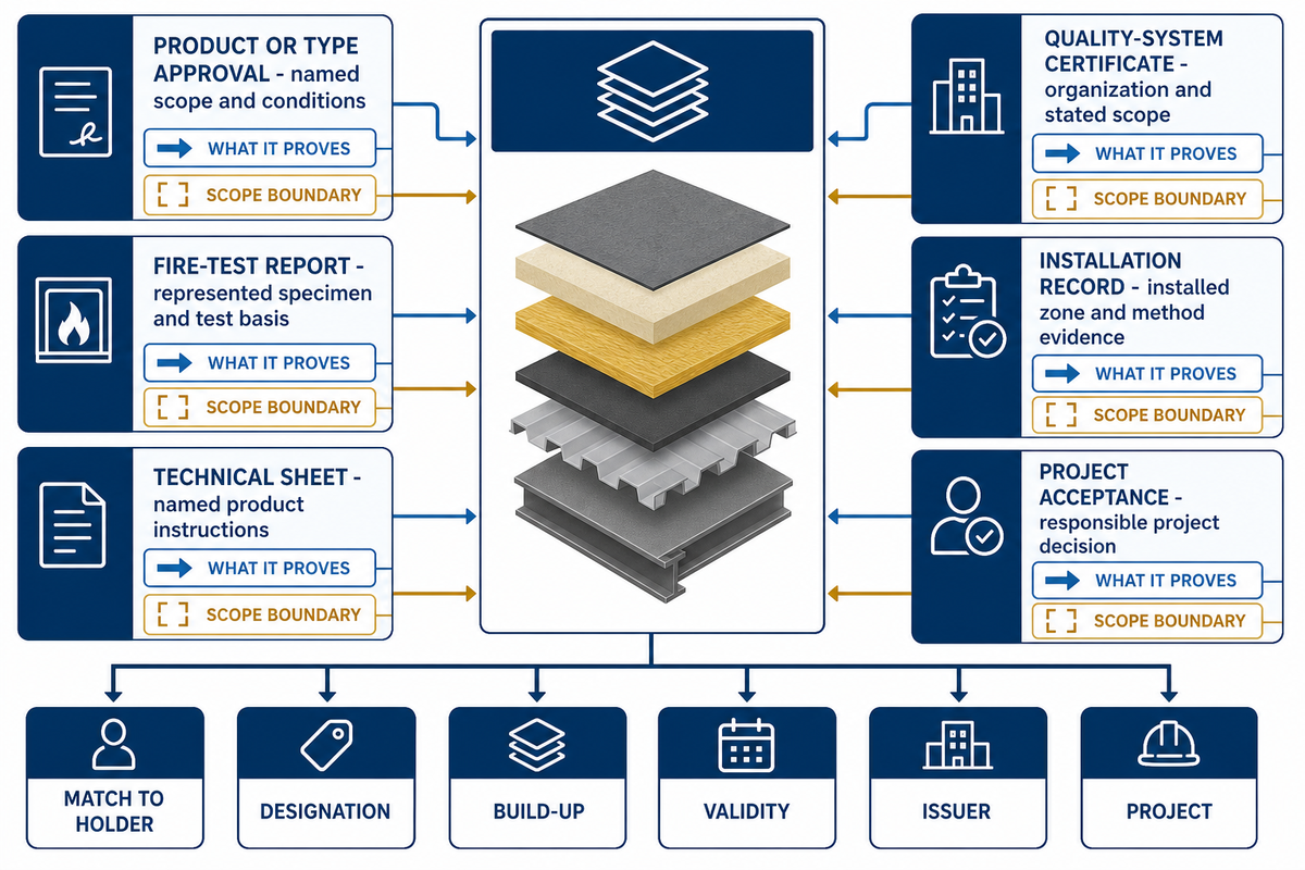
A statement of approval on a product page can’t be considered approval for the installation of a deck. Ask for the exact holder, product designation, intended use, tested construction or specimen, substrate, thickness, surface finish, limitations, validity, issuer, applicable flag or conformity route, and the party reviewing the project.
“provides the international requirements for laboratory testing, type approval and fire test procedures for products referenced under SOLAS chapter II-2.”
The quotation should distinguish a product or type-approval certificate, fire-test report, technical sheet, organizational quality-system certificate, batch identity, installation record, and project acceptance. For construction that includes several components, evidence from one layer tested separately may differ from the evidence needed for the combined construction. The USCG and Federal Approval Process language may be used as a reference, but may not provide a global solution for all flag state or project approvals.
Consider primary deck build-up evidence to understand the function of adjacent layers and then compare it to the entire marine deck covering system. The supplier should map the documents to the proposal rather than moving a logo or certificate statement across various primers, thicknesses, substrates, or finishes.
Situations That Justify Rejecting Either Route: 2-Route Veto Matrix
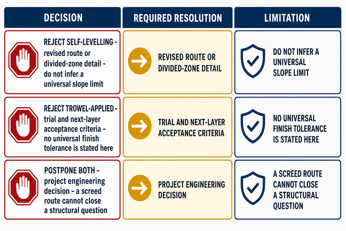
Avoid a route when a given project duty interferes with its named-product or workfront limitations. Postpone both routes until the inputs required for comparison are available. A stop decision is safer than selecting a method only because the schedule is under pressure. The United Kingdom crew-accommodation notice illustrates why drainage and wet-space floor duties can veto a generic route choice.
| Decision | Source-backed reason | Required resolution | Limitation |
|---|---|---|---|
| Reject self-levelling | The required formed geometry cannot be maintained within the named system | Revised route or divided-zone detail | Do not infer a universal slope limit |
| Reject self-levelling | Continuous placement, boundary, or mixing control is unavailable | Executable workfront plan | Product and zone specific |
| Reject trowel-applied | Manual workfront cannot control the broad area within the stated working window | Crew, zoning, or alternative route | Needs method evidence, not a generic labour assumption |
| Reject trowel-applied | The proposed hand finish cannot meet the required receiving-surface condition | Trial and next-layer acceptance criteria | No universal finish tolerance is stated here |
| Postpone both | Structural adequacy or deck movement has no responsible owner | Project engineering decision | A screed route cannot close a structural question |
| Postpone both | Approval, finish interface, passenger access, or drainage geometry remains unresolved | Complete build-up and authority review | No certificate transfer by similarity |
Use These Inputs for a Two-Route Screed Comparison
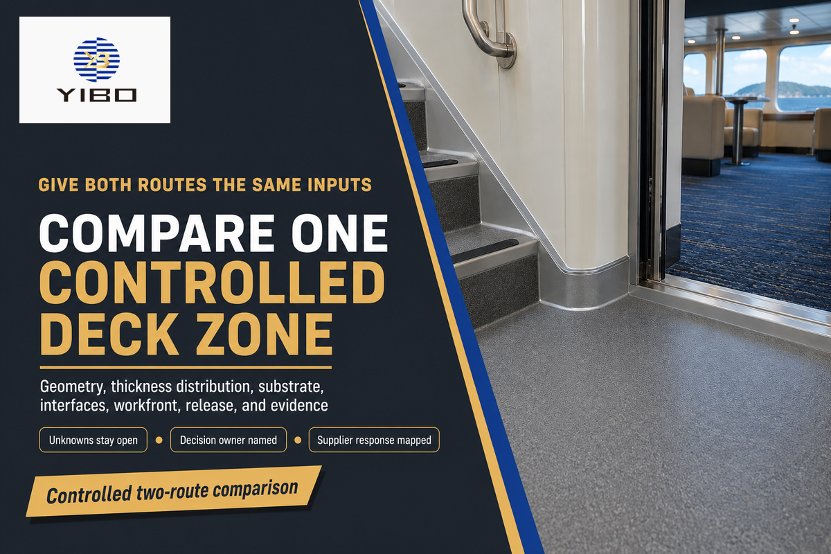
Use the same geometry, interfaces, release definitions, and evidence scope in one controlled deck-zone input to compare both placement routes; leave unknown fields open for their decision owner. For any unknown geometry or interface, mark the field open rather than treating this route comparison as a complete request-for-quotation input pack. Assign an owner, set a decision date, and leave the lines open for now. The United States primary-deck-covering approval procedure illustrates why product designation, intended use, test reports, and inspection arrangements belong in the evidence request.
| Comparison field | Controlled input | Supplier response | Review use |
|---|---|---|---|
| Deck-zone identity | Vessel, drawing and zone reference | Scope acknowledgement | Keeps offers on one boundary |
| Finished geometry | Flat, fall, feather or divided zone | Proposed placement route | Tests route fit |
| Thickness distribution | Surveyed minimum, typical and maximum | Layer schedule | Checks named-product range |
| Substrate condition | Material, coating and retained layers | Preparation response | Controls interface risk |
| Primer and interfaces | Named adjoining materials | Compatible system proposal | Prevents assumption transfer |
| Placement workfront | Boundaries, access and adjacent trades | Executable method basis | Checks site feasibility |
| Material logistics | Batch, water, pump or hand-carry route | Crew and equipment plan | Exposes workfront constraints |
| Release milestones | Work, access, next layer and service | Named criteria and records | Makes schedules comparable |
| Evidence package | Designation, scope, validity and tested build-up | Document map to proposal | Frames approval review |
| Parameter | Required value or range | Why it matters | How to verify |
|---|---|---|---|
| Vessel and zone | ID, use, flag or route | Frames applicability | Controlled project register |
| Finished geometry | Flat, fall, feather, or divided zone | Shortlists placement route | Approved drawing and datum survey |
| Thickness distribution | Surveyed min/typical/max in mm | Tests named-product layer strategy | Point file linked to drawing revision |
| Substrate and interfaces | Material, coating, drains, thresholds, retained layers | Controls preparation and compatibility | Survey, photographs, responsible sign-off |
| Workfront | Access, batch route, utilities, ventilation, shift | Tests placement feasibility | Joint logistics walkdown |
| Release milestones | Work, walk-on, next layer, service | Makes schedule claims comparable | Named criteria and records |
| Evidence pack | Designation, scope, validity, tested build-up, project review | Prevents approval transfer | Issuer database and controlled documents |
Route-selection takeaway
Classify the deck as flat, fall, feather, or a divided combination when assessing the best self leveling marine screed for that controlled zone. Then ask each supplier to map one named product, complete layer build-up, executable workfront, schedule basis, and evidence set to the same controlled inputs.
Send Your Deck-Zone Inputs to Yibo
Share the geometry, thickness map, interfaces, workfront, finish, schedule, and evidence route for a supplier-specific review.
Frequently Asked Questions
Are screed and self-levelling the same?
Answer
No. Screed names a broad layer function, while self-levelling describes a placement behaviour for a named formulation. On a vessel, identify the substrate, zone geometry, layer role, finish, product designation, and applicable evidence before deciding whether the terms point to the same proposed construction. The supplier should explain any narrower catalogue usage in the current proposal.
How thick can self-leveling screed be?
Answer
There’s no universal thickness. Use the current technical document for the exact product and proposed substrate, then compare its minimum, maximum, and multi-layer conditions with the surveyed thickness distribution. Deep points, thin edges, falls, and transitions may require separate details rather than one average value. Record every exception by deck-zone identifier.
What should I put down before self-leveling compound?
Answer
Apply only the preparation and compatible primer specified for the selected product, actual substrate, and approved build-up. Record the surface condition, coating or retained layer, preparation method, primer identity, application window, and any required test. A generic primer recommendation isn’t enough for a marine deck proposal. Keep the verified surface record with the zone file.
What are the disadvantages of self-leveling concrete on a ship deck?
Answer
Flowing routes may be unsuitable where the zone must hold formed falls, boundaries are difficult to control, placement continuity is unavailable, or the measured build-up falls outside the named product’s limits. The correct conclusion is project-specific; “self-leveling concrete” isn’t one universal marine material.
Which marine screed is better for formed falls around drains?
Answer
Trowel-applied underlay is usually the first route to assess because workers can deliberately shape the profile. That’s only a shortlist. The project still needs the drain elevation, intended water path, start and end levels, threshold and passenger-access geometry, substrate, selected finish, thickness map, and current product limits. A self-levelling formulation may permit local trowel work, but one formulation-specific allowance can’t be generalized into reliable fall-forming capability for every product. Divide a mixed flat-and-fall area into controlled subzones when one placement behaviour can’t satisfy both duties, and have the responsible design and approval parties review the completed build-up.
Conclusion
A method label alone does not favour one route: self-levelling and trowel-applied underlays address different geometry and placement duties, so start with the Flat–Fall–Feather Screed Route. Evaluate the shortlisted options based on the work front and confirm the precise thickness of the underlay, the substrate interface, the release timings, and the complete build-up evidence. A controlled deck-zone input pack gives procurement a comparison that can survive technical review.
Editorial transparency
The company history, factory area, product-family descriptions, quality-system statement, and named business relationships supplied for this article are first-party statements from Suzhou Yibo Industry & Trade Co., Ltd. They don’t establish a current product certificate, shipyard contract, patent right, or vessel-specific approval. Product selection and acceptance remain subject to current documents and the responsible project authorities.
References & Sources
- 2010 Fire Test Procedures Code Text Agreed International Maritime Organization
- MSN 1844 (M) Amendment 1: Maritime Labour Convention 2006, Crew Accommodation United Kingdom Maritime and Coastguard Agency
- 46 CFR 164.106: Primary Deck Coverings Electronic Code of Federal Regulations
- Approved Finish Materials and Primary Deck Coverings United States Coast Guard
- 2010 International Code for Application of Fire Test Procedures Government of the Netherlands publication portal
- Approval Finder DNV



![Marine PU Floor: Selection & Installation [Guide]](https://yibomarine.com/wp-content/uploads/2026/09/marine-pu-floor-blog-featured-150x150.png)