
Get in touch with Yibo Company


Updated September 2026
Naval vessel flooring is the complete, location-specific marine flooring build-up accepted for a defined compartment and service condition. Its exposed surface is only one part of the installed system.
Flooring on military ships covers interior accommodation, technical spaces and exposed work areas. Because those areas face different marine environments, a shared label can’t replace a compartment brief.
Before a product name enters the discussion, follow a disciplined planning sequence. Define the compartment duty, map the complete build-up, state what each evidence document proves, close cross-trade interfaces, set release points for concealed work, and retain the accepted configuration for maintenance and refit.
This article is for planning and inspections, and isn’t a product endorsement for Yibo, nor does it provide project specifications, state an approval viewpoint, or replace the naval authority, the owner, the classification society, the flag Administration, the shipyard, or the approved work.
Plan naval vessel flooring from the compartment outward. Freeze the operating duty and structural deck first, then connect each layer, interface, document, installation check and handover record to the exact location where it applies.
Guide boundary at a glance
- This Blog owns system mapping, evidence interpretation, work control, diagnosis and handover methods.
- The existing naval-vessels Page owns Yibo system options, product information, current document scope, project-fit review and quotation.
- Values for thickness, temperature, humidity, cure, traction or inspection frequency must come from the governing project documents.
- A certificate, test report or final photograph can’t prove more than its stated object and scope.
Start With the Complete Floor Build-Up, Not the Visible Finish
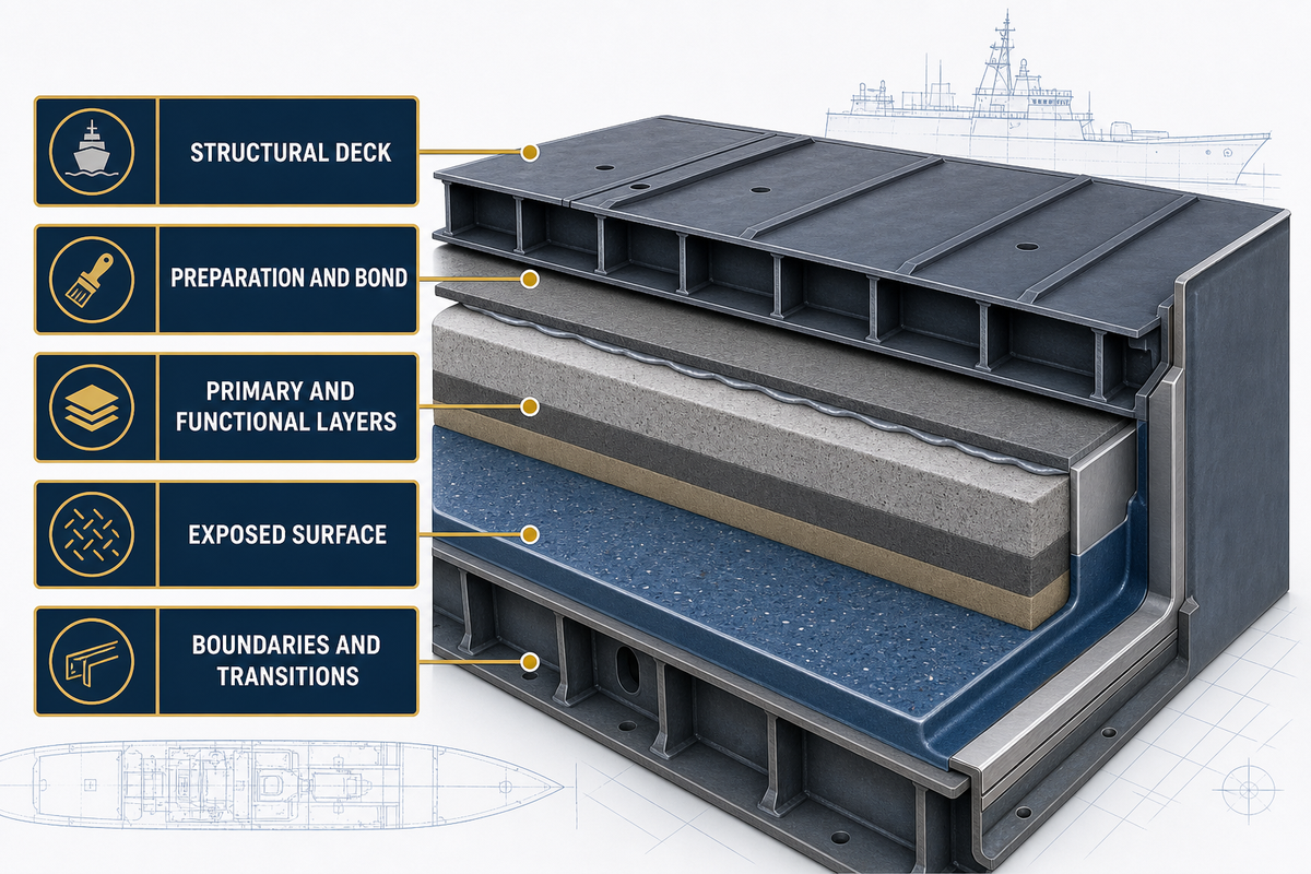
On board, even the word “floor” can hide several different layers. Structurally, the deck carries the floor arrangement. A deck covering may be the first layer applied to a deck, and a floor covering or finish can be applied over it. Adhesives, primers, levelling materials, resilient layers, membranes, load-distribution layers and edge details may all affect the installed construction.
United States Coast Guard finish-material guidance distinguishes primary deck covering from floor covering as related evidence categories rather than interchangeable labels. That distinction shows why a finish name or showroom sample is an incomplete starting point.
What is the floor on a ship called?
In technical briefs, distinguish the structural deck from the first applied layer, every functional layer, the exposed surface and the perimeter details. Drawings and governing documents should decide which term applies to each item, and which evidence controls its acceptance.
| Build-up part | Question to close | Evidence owner | Common false transfer |
|---|---|---|---|
| Structural deck | What condition, material, geometry and retained coating exist? | Structural drawing and deck-release record | A finish claim is treated as proof of substrate readiness |
| Preparation and bond | Which preparation, primer or direct-bond condition applies? | Approved procedure and current product instruction | One preparation recipe is applied to every deck |
| Primary and functional layers | Which layer levels, protects, isolates, damps or distributes load? | Approved build-up and layer-specific documents | One layer inherits another layer’s evidence |
| Exposed surface | Which service, cleaning and traction conditions apply? | Compartment schedule and finish evidence | Appearance is taken as proof of the hidden construction |
| Boundaries and transitions | How are drains, edges, penetrations and adjacent trades closed? | Coordinated details and interface releases | Details are left for the installer to improvise |
Procurement descriptions therefore need to define the complete proposed stack and its boundaries. Labels such as “epoxy,” “floating floor,” “vinyl” or “non-slip deck” still leave the concealed construction, evidence scope and interface responsibility unresolved.
Define the 12-Field Compartment Duty Envelope
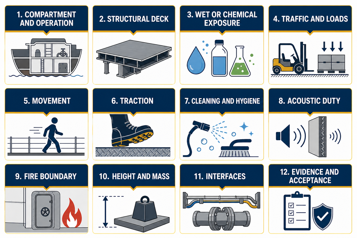
This guide starts with the original 12-Field Compartment Duty Envelope. It isn’t a navy form, classification rule or International Maritime Organization checklist. Its purpose is to bring decisive questions upstream of product selection and identify the owner of each missing input.
Living quarters, workshops, control rooms, wet areas, passageways and equipment zones can sit on one vessel while carrying different loads, cleaning practices, acoustic expectations, fire boundaries and electrical hazards. In an official Navy magazine-decking research topic, location-specific geometry, handling loads and operating demands likewise shape the floor problem. Nothing in that example supplies a universal design for other spaces; the current FY-28 NAVSEA work item is another location-bound example because it distinguishes electrical-grade sheeting across a designated space from local matting at listed hazards.
| Duty category | Input to record | Likely owner | Hold if unknown |
|---|---|---|---|
| 1. Compartment and operation | Space identity, mission use, occupied state and adjacent spaces | Owner and naval architect | Do not generalise from another room |
| 2. Structural deck | Material, condition, welds, distortion, retained layers and repair history | Structure and shipyard production | No preparation release |
| 3. Wet or chemical exposure | Source, frequency, duration, named substances and drainage | Owner, operations and safety | No generic resistance claim |
| 4. Traffic and loads | Foot traffic, wheels, equipment, impact and concentrated loads | Layout, structure and operations | No durability ranking |
| 5. Movement | Joints, vibration, structural flexure and equipment movement | Structure and machinery teams | Escalate layer and interface compatibility |
| 6. Traction | Task, footwear, contaminant, slope and cleaning state | Operations and safety | No “anti-slip” conclusion by label |
| 7. Cleaning and hygiene | Soils, chemicals, tools, frequency and sanitation boundaries | Operations and maintenance | No finish texture decision |
| 8. Acoustic duty | Source, receiver, path, operating state, metric and acceptance owner | Acoustics and owner | No isolated product promise |
| 9. Fire boundary | Applicable vessel, space, construction and evidence route | Fire safety and governing authority | No certificate transfer |
| 10. Height and mass | Build-up envelope, transitions, doors, equipment and weight control | Naval architect and weight control | No layer schedule release |
| 11. Interfaces | Drains, thresholds, penetrations, partitions, foundations and removable plates | Named discipline for each boundary | No workfront opening |
| 12. Evidence and acceptance | Applicable documents, reviews, witnesses, releases and closeout records | Owner, yard quality and governing party | No commercial equivalence decision |
Convert uncertainties into actions instead of assumptions. Treat the field, source document, responsible owner, due date and effect on the workfront as one unit. For example, a blank acoustic duty isn’t permission to copy a value from another vessel. It remains an unresolved input with a named owner.
Separate Material Evidence From Installed-System Approval
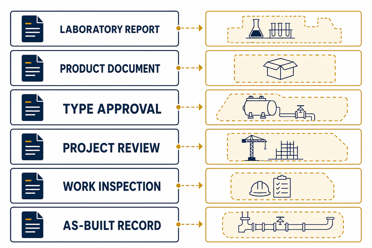
Only after its object is identified does evidence become useful. Under a named method, a laboratory report describes a named specimen. Product or material documents describe the items they name. Type approval records have a holder, construction, basis, validity and limitations. Project review considers proposed use, work inspections record events at a location, and as-built records connect the accepted installation to the vessel configuration.
Under the current electronic Code of Federal Regulations for primary deck coverings, testing, inspections, package identification and type-approval records are distinct parts of an approval route. Current ABS Product Design Assessment text illustrates a different boundary by limiting service, substitutions, flag acceptance and individual-vessel review. Neither source proves approval of an unnamed Yibo system or creates a global naval rule.
| Evidence object | What it can establish | What it cannot establish alone | Read-back fields |
|---|---|---|---|
| Laboratory report | Named specimen, method and reported result | A changed or larger installed construction | Specimen, substrate, layers, conditioning, method, result |
| Product document | Product identity, stated properties and instructions | That the named material was installed correctly | Manufacturer, product, revision, limitations |
| Type approval | Defined holder, construction, basis and conditions | Automatic acceptance by every authority or vessel | Holder, product, issue, expiry, conditions, status |
| Project review | Disposition of a proposed use under project documents | That production matched the reviewed proposal | Drawing, revision, comments, authority, disposition |
| Work inspection | Observed condition or action at a location and time | Unobserved concealed work elsewhere | Location, stage, criteria, witness, finding, action |
| As-built record | Accepted configuration and traceability package | New suitability after an uncontrolled substitution | Location, materials, batches, revisions, deviations, acceptance |
Use a document-precedence ladder
Recency alone doesn’t determine which document controls. FY-28 NAVSEA Standard Item 009-026, dated 6 June 2025, gives a concrete United States Navy example: its item-specific dry-film-thickness, temperature, humidity and surface-preparation requirements take precedence over a conflicting NAVSEA-reviewed ASTM F718, while the NAVSEA-reviewed F718 supersedes another manufacturer F718 even if that other sheet is newer.
Don’t reproduce that hierarchy in another programme. Instead, write the hierarchy for the actual project: invoking work item, approved drawing, specification, reviewed product instruction, method statement and inspection plan. Specify the authority responsible for conflicts so reviewers don’t have to guess from a file date.
Assign Every Layer a Function and an Evidence Owner
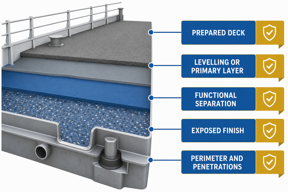
Layer names describe materials, whereas layer functions explain why those materials are present. Preparation creates the required deck condition. Primer or bond layers connect specified materials. An underlayment is used to level or fair the deck. At a defined boundary, a membrane may manage water. Where the acoustic path requires it, resilient or damping layers may provide isolation. Softer layers may need protection from a load-distribution layer. Exposed service duty belongs to the finish.
When an acoustic insulation layer is specified, its accompanying documentation includes evidence for the tested or reviewed assembly and the transmission path. Merely placing a finish above that insulation doesn’t transfer the evidence to the finish.
Rarely does one document own every function. Structural documents govern deck condition; floor-system documents govern compatible layer relationships; acoustic or fire review may govern a tested construction; detail drawings govern boundaries; and the inspection plan governs evidence at each release. Put those owners beside the layer schedule.
| Layer or boundary | Intended function | Evidence owner | Invalid transfer |
|---|---|---|---|
| Prepared deck | Provide the specified substrate condition and geometry | Deck release and preparation procedure | Topcoat data proves deck readiness |
| Levelling or primary layer | Fair, slope or form the first applied construction | Approved build-up and current instruction | Level surface proves adhesion or drainage |
| Functional separation | Address a defined acoustic, thermal or protective duty | Discipline-specific review and tested assembly | Material label proves installed-system performance |
| Exposed finish | Carry traffic, cleaning, texture and appearance duty | Finish schedule and product-specific evidence | Finish approval covers concealed layers |
| Perimeter and penetrations | Maintain continuity and close the service boundary | Interface drawing and installation release | Field sealant choice cannot affect approval |
Electrical duty needs its own classification. Under FY-28 NAVSEA 009-026, electrical-grade sheeting forms a continuous primary deck covering across an entire designated space. By contrast, electrical-grade matting is installed locally over another primary covering at specific hazards. That document also controls seam location, continuity, edges, penetrations and removable deck plates.
The lesson isn’t that every navy must use that construction. It’s that “electrical flooring” can’t be reduced to a loose mat or finish covering. Decide whether the hazard is space-wide or local, identify the governing design, and coordinate every discontinuity before material selection.
Close Interfaces Before the Workfront Opens
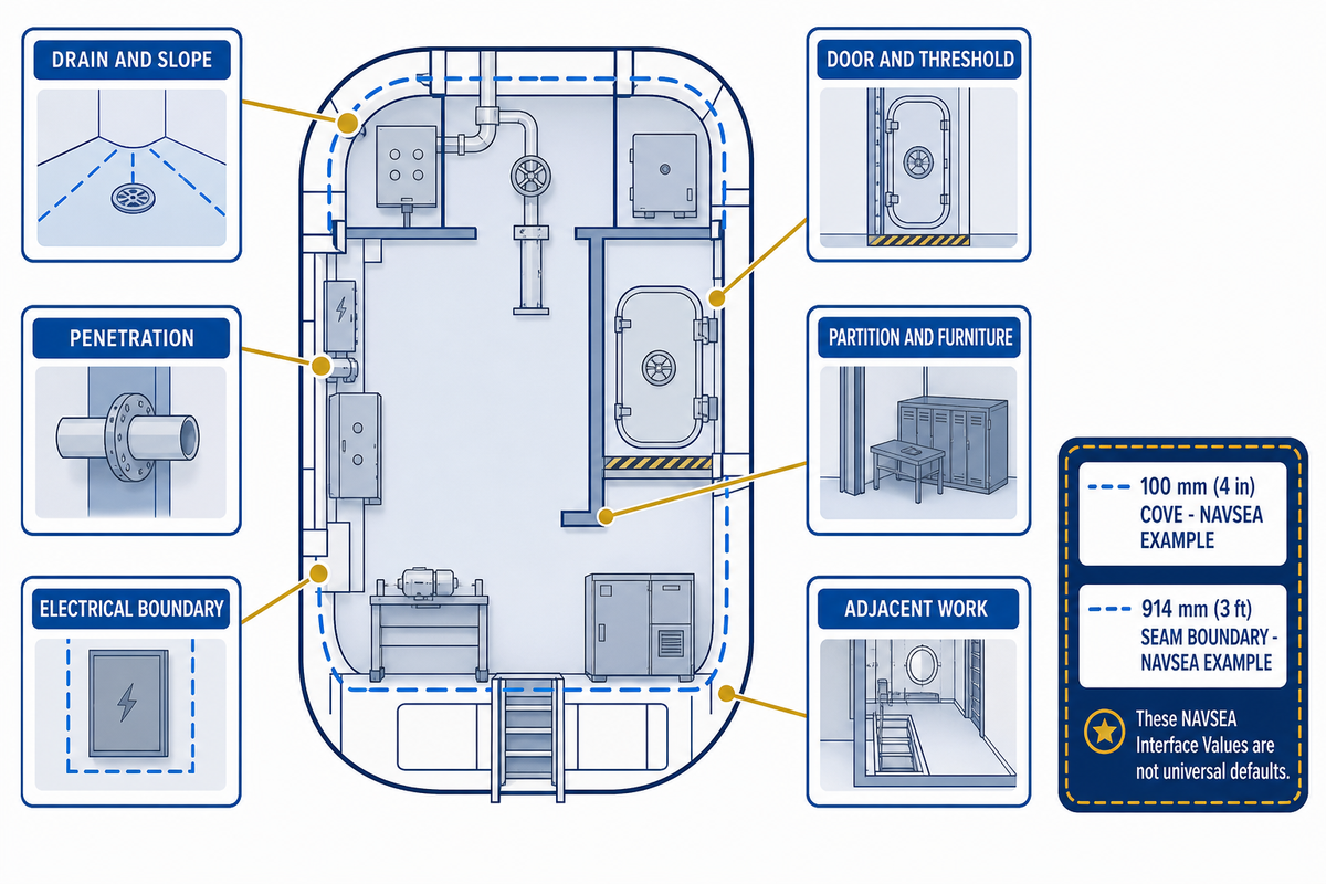
Many failures in flooring systems occur outside of a floor installer’s expected scope. Drain flow may be inadequate. Movement can occur at a penetration after it has been sealed. Thresholds may leave too little build-up height, partition tracks may bridge resilient construction, and removable plates may be bonded shut. Equipment foundations can disrupt coves, membranes or electrical continuity.
An interface register must show the required input, responsible discipline, date due, release condition, and record retention. “Coordinate on site” isn’t a released detail. Useful releases state which drawing is applicable, what must be completed, what inspection determines the release, and what happens if the released detail doesn’t conform to drawing.
| Interface | Input to resolve | Release evidence | Reopen trigger |
|---|---|---|---|
| Drain and slope | Level, collar, flow route, removable cover and waterproof boundary | Flow check, detail and pre-cover photograph | Obstruction, ponding or altered drain geometry |
| Penetration | Movement, clearance, edge treatment and responsible trade | Coordinated detail and inspected boundary | Late cable, pipe or bracket change |
| Door and threshold | Finished level, transition, swing and accessible route | Approved level schedule and clearance check | Build-up or door-set revision |
| Partition and furniture | Load path, isolation break and installation sequence | Coordinated plan and boundary release | Fixing crosses or compresses a functional layer |
| Electrical boundary | Whole-space or local hazard, seam position and removable plate | Hazard classification and continuous detail | Equipment or seam location changes |
| Adjacent work | Hot work, overspray, contamination, access and protection | Area release and protection plan | New contamination or damage after release |
In the current NAVSEA example, drain flow is checked before disturbance and after installation; exposed deck and penetrations are inspected; and deck fittings must remain removable and operational. Use this as evidence that interfaces can belong to the acceptance sequence, while taking actual criteria from the project governing the vessel.
Source-bounded detail: FY-28 NAVSEA 009-026 uses a 100 mm (4 in) cove for its continuous waterproof-membrane example and places a 914 mm (3 ft) seam boundary around listed electrical equipment unless the specified welded-continuity condition is met. These are United States Navy work-item values, not design defaults for another programme.
Likewise, nonskid or non-slip surface descriptions must stay tied to location, contaminant, task, preparation and acceptance method. Wording alone doesn’t establish safe traction in every operating state.
Install and Inspect in Release-to-Concealment Order
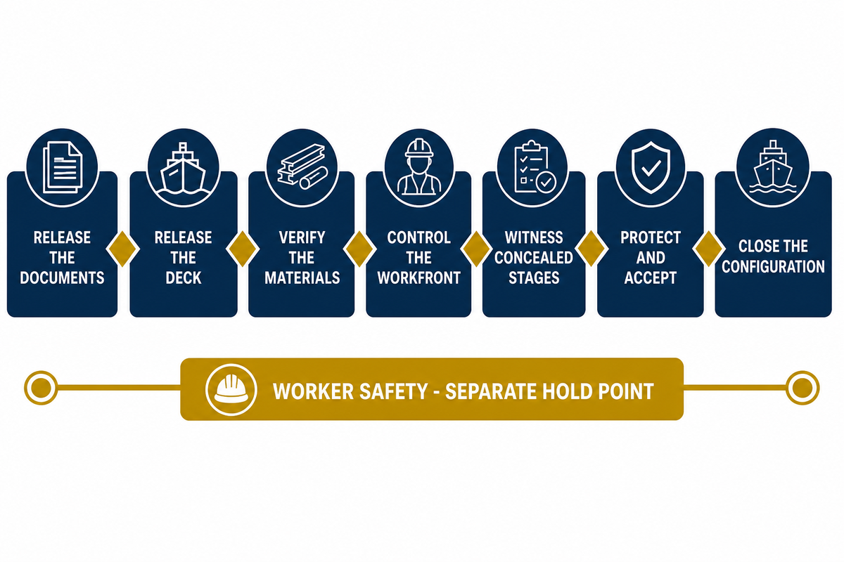
Final visual assessment confirms only what’s still visible. It can’t reconstruct earlier preparation, identify hidden materials, recover missed environmental checks or show how a penetration was sealed before concealment. Inspection planning therefore needs to follow the order in which evidence disappears.
Specify the controlling document revision and exact location. Release deck condition and interfaces, then confirm material identity and storage status. Record the application conditions required by the procedure and witness mixing, placement or layer formation at the specified points. Close interfaces, cure or readiness checks, protection, and final acceptance when assembling the as-built file.
- Release the documents — identify the controlling drawing, work item, procedure, product instruction and inspection plan for the location.
- Release the deck — record condition, preparation, cleanliness, geometry, repairs and every interface while visible.
- Verify the materials — match identity, batch, shelf status and storage to the approved construction and current instructions.
- Control the workfront — confirm environmental, access, ventilation, exclusion and adjacent-work conditions required by the procedure.
- Witness concealed stages — record mixing, layer placement, boundaries, exceptions and responsible release before covering.
- Protect and accept — apply the project’s readiness, drainage, defect, repair and return-to-service checks.
- Close the configuration — connect locations, materials, revisions, deviations, inspections and acceptance in the as-built record.
Worker safety is a separate hold point
Quality control doesn’t replace occupational control. OSHA shipyard coating guidance identifies competent-person atmospheric testing, ventilation that keeps covered vapour concentrations below 10% of the lower explosive limit, applicable gas-free status, ignition-source restrictions, respiratory protection and precautions for adjacent spaces. Actual duties depend on the material, space, task and jurisdiction.
Keep this control plane separate from finished-floor service claims. Even when a material is acceptable in cured service, mixing or application can require strict controls. Conversely, safe application doesn’t prove durability, traction, acoustic performance or vessel acceptance. For each workfront, the method statement should link current safety information to yard procedures.
Inspection principle: place the witness point immediately before the evidence becomes inaccessible. If the record is postponed until the final surface is complete, it may document appearance but not the concealed condition.
Apply the Red-Line Substitution Test Before a Change
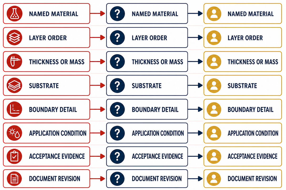
Treat “equivalent” as a conclusion, not a starting adjective. A replacement might satisfy one brochure property and change the identified material, the sequence of layers, their respective thicknesses, the relationship to the substrate, the boundary detail, the application condition or the evidence; the current primary-deck-covering approval route illustrates why formulation, production tests, marking and approval records can’t be collapsed into one generic equivalence claim. Any such changes can trigger a technical review.
The Red-Line Substitution Test is the change control method used in this guide. For each construction item that’s specifically named in the controlling evidence, draw a red line below it. Return the affected question to the evidence owner for justification prior to purchase or installation if a proposal crosses a red line.
| Red line | Reopened question | Evidence owner | Disposition record |
|---|---|---|---|
| Named material | Is the new item within the approved identity and compatibility set? | Product and project reviewer | Accepted, rejected or more evidence required |
| Layer order | Does the tested or reviewed interface still exist? | System designer and approving party | Revised build-up and review |
| Thickness or mass | Does the change alter performance, level or weight control? | Discipline owner | Updated schedule and calculation |
| Substrate | Does bond, movement or preparation evidence transfer? | Structure and floor-system reviewer | Deck-specific approval |
| Boundary detail | Are continuity, drainage and access preserved? | Interface owners | Coordinated detail revision |
| Application condition | Can the yard meet the new workfront requirements? | Production, safety and quality | Revised method and release plan |
| Acceptance evidence | Do current reports and approvals cover the proposal? | Governing authority | Traceable technical disposition |
| Document revision | Which instruction now controls and what changed? | Document control | Revision comparison and issue record |
ABS example text reviewed for this guide limits substitutions and retains individual-vessel review. This supports the position that certificate titles aren’t equivalence waivers. Final decisions belong to the project’s responsible authority, not to this editorial framework.
Use Symptoms to Choose the Next Check, Not the Cause
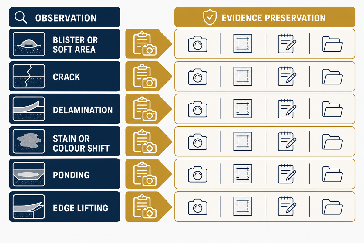
Treat a blister, crack, stain, soft area, lifted edge or ponding location as an observation. Several cause families may be consistent with it: substrate condition, contamination, retained moisture, mixing or cure history, incompatible layers, structural movement, impact, cleaning, drainage or a failed interface. Appearance alone doesn’t distinguish among them.
In a controlled 2026 coating-adhesion study, adhesion changed substantially between clean, corroded and oil-contaminated steel specimens. Those results belong to the tested primers, preparation, contaminants and methods. Their value here is methodological: substrate evidence matters, and one controlled study can’t establish a universal naval acceptance limit.
| Observation | Possible families | Preserve first | Next discriminating check |
|---|---|---|---|
| Blister or soft area | Moisture, gas, mixing, contamination or cure | Map, timing, batch and condition records | Locate the affected layer and compare process history |
| Crack | Deck, joint, shrinkage, impact or movement | Ends, direction, width and structural context | Compare the crack with deck and joint records |
| Delamination | Substrate, intercoat, contamination or movement | Failure plane and adjacent sound area | Identify where separation occurred before widening repair |
| Stain or colour shift | Spill, cleaning, exposure, batch or repair edge | Substance, lighting, cleaning and batch history | Separate appearance from a service-affecting change |
| Ponding | Deck geometry, levelling, drain or obstruction | Levels, flow path, drain state and prior checks | Joint review with the deck and drainage owners |
| Edge lifting | Impact, water path, preparation or boundary detail | Edge construction and nearby service history | Trace the boundary and separation plane |
Do
- Map the symptom to a compartment grid and drawing revision.
- Retain the failure plane, samples, batches and process history.
- Choose checks that separate competing explanations.
- Define the evidenced repair boundary before removal.
Don’t
- Assign root cause from a photograph alone.
- Use one laboratory value as a vessel-wide limit.
- Destroy the boundary before responsible parties record it.
- Cover a repaired area before its release is documented.
Plan Maintenance and Refit Around the Accepted Construction
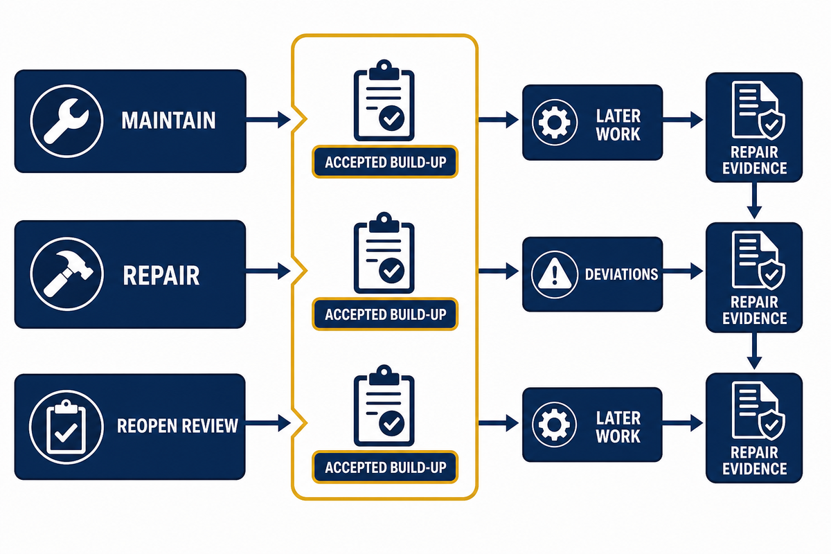
Maintenance relies on the accepted layer schedule rather than finish colour alone. The crew should understand the service soil, cleaning method, triggers for inspection, allowed local repair, and treatment of the boundary and the routine for escalation. Unknown repair chemistry or an uncontrolled penetration can change the construction even when most of the floor remains intact.
Ease of maintenance is a defined service question, not a brochure adjective. No cited source supplies a universal shipboard inspection interval or service life, and a seamless appearance doesn’t predict wear and tear. Record the interaction of the accepted texture and the repair boundary with routine abrasion, cleaning, spills, and delayed access.
Three decisions define the maintenance boundary. Maintaining the accepted construction shouldn’t cross a red line. A bounded repair is the restoration of the designated layers and interfaces by an approved method. Wider technical review is needed when the substrate, layer schedule, exposure, boundary, approval scope or failure extent remains uncertain.
| Decision | Use when | Minimum record | Escalate when |
|---|---|---|---|
| Maintain | The accepted surface and boundaries remain sound | Condition, cleaning and observation history | Damage exposes or questions another layer |
| Repair | The affected layer and boundary are evidenced and bounded | Cause, extent, method, materials, witness and reinspection | Extent grows or compatibility remains uncertain |
| Reopen review | A red line, evidence scope or configuration changes | Technical query, revised detail and authority disposition | Do not proceed until the responsible owner decides |
NAVSEA maintenance-planning material describes revision, task-completion, feedback and configuration records in a broader maintenance context. Applied to flooring, the useful discipline is continuity: accepted build-up, later work, deviations and repair evidence should remain connected. That source doesn’t provide a universal inspection interval or service life.
Build the Handover Brief Without Recreating the Solution Page
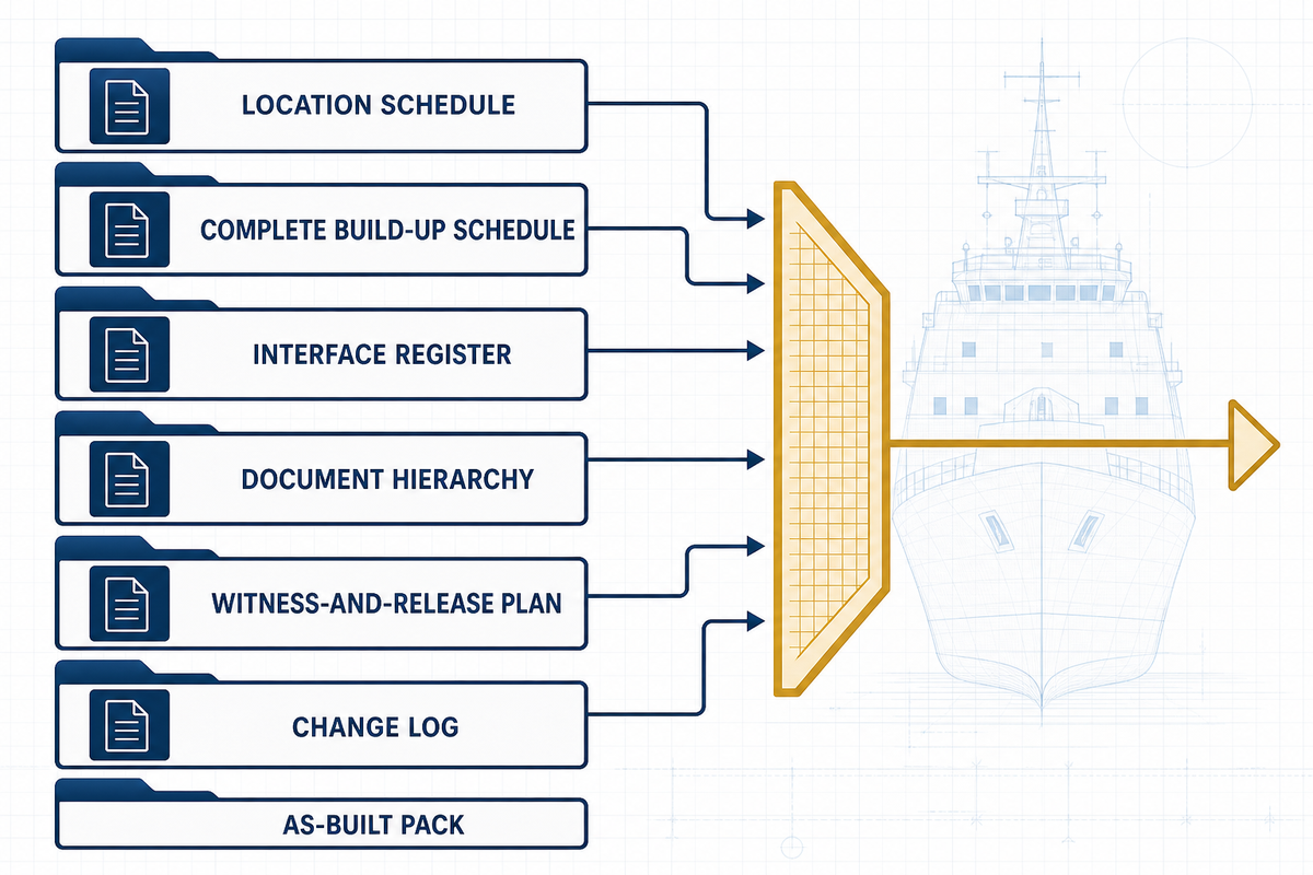
Useful commercial briefs let each supplier review the same duty while technical authority stays with the project; the location, material, inspection, exception and report fields in the current FY-28 NAVSEA work item illustrate why a procurement handover needs traceable objects instead of a finish label alone. Include the compartment list, service conditions, structural deck, governing documents, height and mass constraints, layer duties, finish exposure, interface register, approval-evidence request, drawing revision, witness plan, traceability requirements, nonconformance route, repair basis and as-built deliverables.
Don’t begin with “quote your best naval flooring”. That wording invites bidders to price different layer stacks, assumptions and evidence. Issue a gap list with the brief, and require each response to state what is included, excluded, assumed, substituted or still awaiting an owner decision.
Neutral handover checklist
- One location schedule tied to current drawings and compartment duty fields
- One complete build-up schedule with layer functions and evidence owners
- One interface register covering drains, penetrations, thresholds, partitions, foundations and removable plates
- One document hierarchy with revisions, review status and conflict owner
- One witness-and-release plan for all work that will become concealed
- One change log linking substitutions, nonconformities, repairs and final dispositions
- One as-built pack connecting material traceability, locations, inspections and maintenance instructions
Once the neutral package is ready, procurement teams can move to Yibo’s naval vessel flooring solutions Page for system options, current document review, project-fit discussion and quotation. Keeping that handoff late and explicit prevents this planning guide from duplicating the commercial Page.
According to the company profile supplied for this article, Yibo is a Suzhou manufacturer founded in 2001 whose range includes floating floors, self-levelling deck coverings, damping coatings, ordinary deck coverings, polyester primary coverings, polyurethane levelling coverings and imitation teak flooring. Because the captured current About page didn’t independently substantiate the profile’s detailed facility, certification and named-shipyard claims, this guide doesn’t use those statements as proof of a product, approval or vessel outcome. Before relying on that scope, buyers can review Yibo’s marine flooring applications hub, marine deck covering systems, marine floating floor systems and marine resin floor systems, then verify the current legal entity, product identity, document holder, validity and project applicability.
Discuss Your Compartment Brief with Yibo
Key takeaway
Handover packs should let reviewers trace one compartment from duty and drawing to build-up, interfaces, controlling documents, concealed-work records, final acceptance and later repairs.
Why This Guide Draws a Hard Boundary
Naval vessel flooring decisions combine deck condition, compartment duty, approval scope and shipyard evidence. This guide translates those inputs into reviewable planning records while leaving product configuration and project acceptance to the responsible parties. Company statements are kept attributed and are never used to prove an unnamed system. Reviewed by the Suzhou Yibo Industry & Trade Co., Ltd. technical team.
Frequently Asked Questions About Naval Vessel Flooring
These answers organise the decision without prescribing an unnamed product. Responsible project documents and authorities determine the final requirements.
What is the best naval vessel flooring?
No single naval vessel flooring system is best for every compartment; the right choice must match the structural deck, exposure, loads, movement, cleaning, acoustic and fire duties, interfaces, approval route, installation controls and handover evidence.
Selection begins with the compartment duty, structural deck, exposure, traffic and loads, movement, traction, cleaning, acoustic duty, fire boundary, height and mass, interfaces and acceptance route. Compare complete build-ups against that same brief. Finishes suited to a dry office don’t automatically answer a wet working area, electrical hazard, machinery boundary or acoustic path. Ask each proposer to return a layer schedule, interface assumptions, document scope, installation controls, witness points and unresolved inputs. Best-supported options are the ones whose full construction answers the same duty and can be installed, inspected, repaired and handed over within the project’s actual constraints.
When should naval vessel flooring be replaced?
Naval vessel flooring replacement scope should follow the evidenced defect boundary and accepted construction, not appearance alone; teams should widen removal only when substrate, hidden-layer, contamination, movement, compatibility or approval evidence shows that a bounded repair cannot restore the required duties.
Map the symptoms, identify the affected layer or interface, review service and repair history, and determine whether a compatible bounded repair can restore the required duties. Widen the scope when the substrate, hidden layers, contamination, movement, approval envelope or damage extent is uncertain. No universal age or life-expectancy value can decide every vessel.
How much does naval vessel flooring cost?
Useful cost comparisons require the same complete scope, access conditions and evidence deliverables, including removal, deck preparation, complete layer build-up, environmental controls, inspection, documentation, return-to-use restrictions and the risk of reopening concealed work.
Define removal and waste, deck preparation, access, compartment geometry, layer build-up, boundaries, materials, labour, environmental and safety controls, cure or return-to-use restrictions, inspection, documentation and the risk of reopening finished work. Two prices per unit area may describe different constructions. This guide therefore doesn’t publish an unsupported universal price range.
Does a certificate approve the complete installed floor?
Certificates approve only the holder, object, construction and conditions stated in their scope; project teams must separately confirm applicability to the proposed vessel, compartment, substrate, layer order, permitted variations, installation controls and as-built acceptance route.
Read the named material or assembly, substrate, layer order, tested specimen, method, results, limitations, validity and permitted variations. Then confirm whether the governing authority accepts that record for the proposed vessel, compartment and installation. Project review, material traceability, in-process inspections and as-built acceptance remain separate evidence objects.
Which records belong in a naval flooring handover pack?
Handover packs should connect each compartment to its accepted build-up and production evidence, including current drawings, layer schedules, material traceability, application records, interface details, concealed-work photographs, inspection results, substitutions, repairs, final acceptance and future maintenance instructions.
Include the duty schedule, structural deck release, current drawings, layer schedule, material and batch traceability, storage and application records required by the procedure, interface details, witness and hold-point records, photographs tied to locations, nonconformities, substitutions, repair dispositions, final inspections, acceptance records, cleaning instructions and future repair information. Keep document revisions and responsible approvals visible.
Conclusion
Naval vessel flooring becomes manageable when the project treats it as a traceable construction rather than a finish label. Define compartment duty, assign every layer and interface, read each evidence document within its scope, control substitutions, inspect before concealment and preserve the accepted configuration. This will result in a common technical object for the design, procurement, fabrication, inspection, and maintenance teams.
References & Sources
- Approved Finish Materials and Primary Deck Coverings United States Coast Guard
- 46 CFR Subpart 164.106: Primary Deck Coverings Electronic Code of Federal Regulations
- NAVSEA Standard Item 009-026, FY-28 Naval Sea Systems Command
- Shipyard Employment: Painting and Other Coatings Occupational Safety and Health Administration
- Product Design Assessment Record American Bureau of Shipping
- Lightweight Magazine Decking Research Topic N093-216 United States Navy Small Business Innovation Research Program
- Effect of Corrosion and Oil Contamination on Epoxy-Primer Adhesion to Steel Progress in Organic Coatings
- Maintenance Planning and Life Cycle Support Naval Sea Systems Command
- Resolution MSC.337(91): Code on Noise Levels on Board Ships International Maritime Organization


![Marine PU Floor: Selection & Installation [Guide]](https://yibomarine.com/wp-content/uploads/2026/09/marine-pu-floor-blog-featured-150x150.png)