
Get in touch with Yibo Company


Updated September 2026
Commercial marine flooring is an installed system built over the structural deck and extending beyond the visible surface. Its performance depends on the structural deck, preparation, primers or adhesives, levelling and load-spreading layers, resilient elements, finish, joints, penetrations, thresholds, and the records connecting that build-up to a defined vessel space.
This field guide is concerned with nine project controls starting with the requirement formulation and ending with handing over the system. It provides naval architects, shipyards, outfitters, inspectors, and owners a way to define the requirements for “marine grade,” “approved,” or “acoustic,” etc. This guide doesn’t rank flooring brands, quote a universal build-up, or replace flag, class, owner, designer, or product documents for a specific ship.
Key takeaway
Control the floor as a named assembly in a named space: every layer, interface, inspection, result, and approval must point back to the same project configuration.
1. Define the Floor System, Not Just the Visible Finish
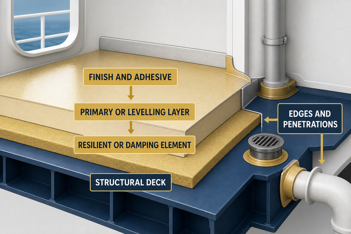
A useful specification is based on separating the structural deck and the primary deck covering as well as load distribution or leveling layers, resilient layers, adhesives, an exposed finish, and edge detail. These terms may overlap in a particular approval pathway, so the project team must state which layer performs which function and on what document it’s based.
“All materials located above the primary deck covering are considered ‘floor coverings’.” United States Coast Guard guidance
The quotation is useful because it makes one category boundary visible. That Coast Guard page also states that an approved primary deck covering may be used as a floor covering without additional testing in its specified route. This is a defined overlap and in no way should be construed to imply that all of the underlayment, finish, adhesive, and assembly may be treated as interchangeable.
Write the build-up from steel upward. For each layer, include function, product identifier, nominal design thickness where the approved or project document specifies one, attachment method, interface owner, and acceptance evidence. Include in the system description the boundaries of the floor where it meets a partition, door sill, drain, equipment foundation, cable penetration, wet-area upstand, or expansion joint.
| Layer or interface | Required function | Identity to freeze | Evidence question | Release owner |
|---|---|---|---|---|
| Structural deck | Carry project loads and receive the system | Material, condition, geometry, coating state | Was the surveyed substrate the specified one? | Shipyard or named inspector |
| Primary or levelling layer | Deck protection, geometry, load transfer, or named combination | Product, batch, thickness rule, preparation | Does the approval or method cover this layer and use? | Flooring contractor and inspection authority |
| Resilient or damping element | Control a defined vibration or sound path | Material, density or grade, joints, perimeter | Does the evidence represent the same assembly and boundaries? | Acoustic designer and shipyard |
| Finish and adhesive | Wear, cleanability, appearance, grip, attachment | Exact finish, backing, adhesive, seam method | Are the finish and adhesive within the represented build-up? | Outfitting and owner teams |
| Edges and penetrations | Preserve separation, drainage, hygiene, or fire boundary | Detail drawing and trade interface | Who inspects the detail before it is concealed? | Interface owner named in the plan |
Decision Capsule: naming a material isn’t describing a floor system. At minimum, the decision record ties one layer record to a deck condition, a space schedule, interface drawings, installation controls, and an evidence set representing the same build-up.
2. Freeze the Vessel-Space Inputs Before Comparing Systems
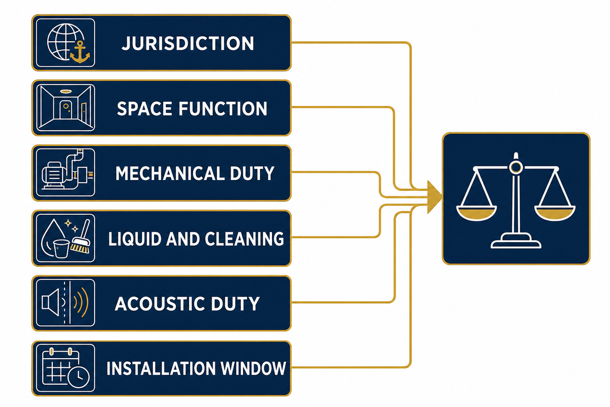
Floor selection is justifiable only after the space and service case are finalized. Capture the vessel’s flag and type, newbuild or refit status, voyage or service, compartment use, traffic, loads, liquid and cleaning exposure, noise duty, fire boundary, geometry, access, schedule and the documents that control acceptance.
Applicability is a gate, not a footer. International Maritime Organization material describes the Safety of Life at Sea Convention rules for passenger ships in international service, while its noise code has its own ship-status, size, type, measurement, and survey boundaries. Neither source provides a complete commercial marine floor specification.
For cruise ships entering the US market, the Centers for Disease Control and Prevention’s Vessel Sanitation Program provides plan review, consultation, and construction inspection for areas within its scope. That program does not approve flooring products. It adds project questions about cleanable details, water management, food-service interfaces, and the construction shown in submitted plans.
| Input field | Question to answer | Evidence source | Owner |
|---|---|---|---|
| Jurisdiction | Which flag, statutory, class, owner, and yard documents control? | Contract, class notation, rules, approved drawings | Owner and designer |
| Space function | Cabin, corridor, galley, machinery space, wet unit, public room, or deck? | General arrangement and room data sheet | Naval architect |
| Mechanical duty | What point, rolling, impact, or distributed loads and movements occur? | Equipment schedule and structural design basis | Structure and outfitting teams |
| Liquid and cleaning | Which fluids, temperatures, dwell times, cleaning agents, and drainage states occur? | Operating and sanitation plan | Operator and hotel team |
| Acoustic duty | Which source, receiving space, path, operating case, and criterion matter? | Noise-control plan and survey method | Acoustic specialist |
| Installation window | What deck condition, climate control, access, cure window, and follow-on work are available? | Build schedule and method statement | Production planner |
The space schedule should have a version control system. If a pantry becomes a wash-down area, a cabin becomes a treatment room, or heavy equipment is added, the floor decision must return to the affected service, detail, and evidence rows. A last-minute label change doesn’t update the assembly by itself.
Applicability capsule: when citing a rule or approval, include six items: flag, vessel type and status, voyage or service, build or conversion status, space use, and controlling project documents. A missing item is a review action, not an invitation to guess.
3. Build a 6-Field Marine Floor Control Map
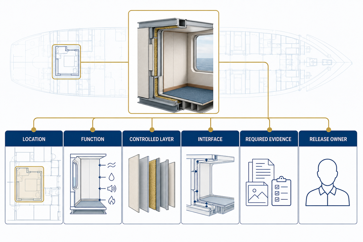
The Marine Floor Control Map is a worksheet for a project that aligns every location with a function, system layer, interface, evidence, and release owner. It converts a finish schedule into a coordination record, so a change in one trade can be traced to the floor details it may disturb.
This is an editorial method, not a class-society form. Start with locations where several duties meet: cabin-to-corridor thresholds, galley drains, sanitary-unit upstands, stair landings, machinery-room equipment bases, partition lines, door tracks, and transitions between floating and rigid construction. Assign an owner to every decision that will later be concealed.
| Location | Function | Controlled layer | Interface | Required evidence | Release owner |
|---|---|---|---|---|---|
| Cabin perimeter | Preserve intended acoustic separation | Resilient layer and load-spreading layer | Partition base, services, skirting | Detail, material identity, photo, inspection sign-off | Acoustic and outfitting leads |
| Galley drain | Drain liquid and retain cleanable geometry | Levelling, finish, sealant, upstand | Drain body and equipment plinth | Falls survey, detail, sealant record, water test if specified | Hotel and piping leads |
| Fire door threshold | Maintain door operation and boundary detail | Entire build-up at transition | Sill, door leaf, adjacent finish | Approved detail, height check, operation test | Joiner and fire-control owner |
| Equipment foundation | Carry load without unintended bridge or damage | Deck covering, isolation boundary, finish | Foundation, bolts, grout, pipe supports | Load input, detail, release inspection | Mechanical and structural leads |
| Open-deck transition | Manage water, movement, traffic, and edge exposure | Preparation, body layer, finish, termination | Coaming, scupper, adjacent coating | Weather detail, preparation record, edge inspection | Deck and coatings leads |
The map also limits change propagation. If a partition foot is changed, the team reviews rows where the foot interfaces with a resilient layer. If a drain body changes, the galley and wet-unit rows reopen. This is a more precise approach than saying “flooring may be affected.”
Control-map capsule: When the fields of a record are left blank, they impede production, because the gap in the record doesn’t have a defined path to closure. Control-map capsule: Fields are location, function, layer, interface, evidence, and release owner.
4. Read Approvals and Test Reports with a Floor Evidence Passport
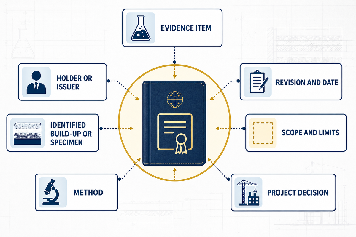
Within its stated scope, a certificate or test report supports only the configuration and decision it names. The Floor Evidence Passport captures the information about the evidence; the issuer, the described product, method, and revision, as well as the limitations of the scope and the specific project decision for which this evidence is presented.
For example, the current United States primary-deck-covering route in 46 CFR subpart 164.106 is tied to defined products, intended use, tests, inspections, and an approval period of 5 years. This example is exclusively the USA, and it illustrates the reason why for a current certificate, the product, use, build-up, and the project have to match.
Acoustic evidence will also need discipline. A peer-reviewed ship study reported a 7 dB change for a particular lightweight floating-floor arrangement, but that measured case doesn’t become a promised reduction for another vessel, boundary, frequency range, or installation. The International Maritime Organization noise code relies on shipboard measurement and survey records; it does not select a commercial flooring product.
Values recorded from the International Maritime Organization’s noise code demonstrate how measurement evidence keeps its operating and spatial context, and aren’t specifications for flooring products, universal survey instructions, or acceptance criteria for all vessels. Actual tasks are determined by the applicable code, Administration, survey plan, and competent specialist.
| Evidence type | Numeric context in the code | Record implication | Floor-project boundary |
|---|---|---|---|
| Propulsion condition | Normal service speed and at least 80% of maximum continuous rating unless another stated provision applies | Record the actual propulsion state | Do not compare surveys from unlike operating states |
| Sea and weather | Wind force 4 and 1 m wave height should not be exceeded under the stated measurement provision | Record exceptions and actual conditions | Weather can alter the evidence, not the floor label |
| Frequency coverage | Octave bands may extend from 31.5 Hz to 8,000 Hz when needed | Retain metric and band range | A single overall figure can hide route differences |
| Reading duration | Stable readings or a period of at least 15 sec | Retain the time basis | A spot observation may not represent variable operation |
| General microphone height | Between 1.2 m and 1.6 m from the deck unless otherwise stated | Record the measurement position | Position belongs to the result |
| General point spacing | At least 2 m between points, no more than 10 m intervals in named large spaces, and not closer than 0.5 m to a boundary | Plot points on the arrangement | Boundary proximity can change interpretation |
| Intake and exhaust geometry | Avoid a 30° gas-stream angle and keep at least 1 m from the opening edge where possible | Retain source geometry | Do not attribute source-field effects to a floor |
| Machinery positions | Measurements at 1 m from machinery, 1.2 m to 1.6 m above deck, and intervals no greater than 3 m in the stated route | Identify machine and point | Separate equipment radiation from receiving-space evidence |
| Accommodation sweep | Move the microphone over 1 m, with a stated ±0.5 m allowance | Retain the spatial averaging route | One convenient point may not represent the room |
| Cabin sample | Not less than 40% of crew cabins, subject to the code’s stated context | Record the selection logic | The sample must represent the vessel, not the flooring catalogue |
| Instrument verification | Calibrator and meter verification at least every 2 years | Keep current instrument records | An untraceable instrument weakens the result |
| Small test area rule | For named field sound-insulation calculations, an area below 10 m² is treated as at least 10 m² | Retain the calculation convention | This is not a minimum floor installation area |
| Exposure duration | The code discusses 8 hours, 24 hours, and a stated 4 hours continuously within its exposure provisions | Separate exposure from room acceptance | Neither measure is a floor product rating |
| High-level stay example | A 10 minutes stay notation appears within a defined warning-sign band | Keep the complete warning context | Do not detach the time from the noise condition |
Notice how 80%, 31.5 Hz to 8,000 Hz, 15 sec, 1.2 m to 1.6 m, 40%, and an instrument-verification interval of 2 years each answer a different evidence question. None describes floor thickness or a guaranteed product result. Project teams should apply the same discipline to every number submitted for a flooring system.
| Evidence item | Holder or issuer | Identified build-up or specimen | Method | Revision and date | Scope and limits | Project decision |
|---|---|---|---|---|---|---|
| Type approval | Named authority | Exact product, associated primer or adhesive, intended use | Cited approval route | Current issue and expiry | Jurisdiction, product, use, conditions | Accept or raise deviation for this layer |
| Fire-test report | Named laboratory and sponsor | Substrate, layers, thicknesses, attachments | Named test method | Report and revision date | Specimen and classification limits | Represented assembly or gap |
| Acoustic report | Designer, yard, laboratory, or research team | Deck, floor build-up, boundaries, receiving space | Metric, positions, operating case | Report date and configuration | Frequencies, equipment state, uncertainty | Design input, comparison, or acceptance |
| Application record | Contractor and inspector | Installed location, batch, layer, interface | Project inspection plan | Shift and timestamp | Recorded conditions and deviations | Release hidden work or repair |
Even a valid supplier test may fail to address the project question. Possible missing links include a different substrate, thickness, adhesive, top finish, fire boundary, test metric, or intended use. Record this as a scope gap. Don’t “average” unlike documents into a new performance value.
Evidence capsule: keep the represented build-up, test method, revision, date, limits, and project decision on one record. A 7 dB result and a 5-year approval period are useful only in their respective evidence envelopes.
5. Sequence Installation Around Interfaces and Release Points
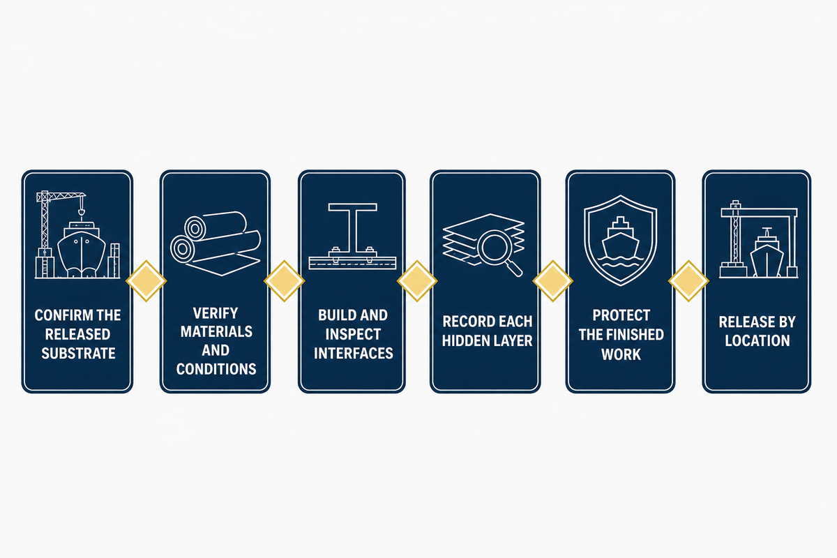
Control over the installation process begins before mixing and laying of the sheeting. Project teams must survey and approve the deck prep, confirm materials and environmental limits, construct interfaces in the proper sequence, inspect each concealed stage, protect completed work, and hold off subsequent trades until all required records are complete.
- Confirm the released substrate — match the surveyed deck, coating state, geometry, cleanliness, and damage status to the method statement.
- Verify materials and conditions — record exact products, batches, shelf-life status, mixing equipment, and specified environmental readings.
- Build and inspect interfaces — complete perimeters, drains, foundations, thresholds, partitions, and penetrations in the agreed trade sequence.
- Record each hidden layer — capture preparation, application, dimensions required by the project, photos, deviations, and responsible sign-off before concealment.
- Protect the finished work — define access, temporary covering, traffic, point-load, contamination, and cleaning restrictions for follow-on trades.
- Release by location — hand over only the mapped area and record unresolved punch items instead of treating the whole deck as complete.
Environmental and safety instructions must come from the chosen product documents, method statement, yard controls, and governing jurisdiction. One manufacturer’s land-based coating guide cites a moisture-screening value of 3 lb per 1,000 ft² per 24 h, but this value isn’t a marine-deck criterion and must not be used in a ship specification. Its value here is to show how easily a unit-bearing number can escape its substrate and method.
Work-area controls during application are also separate from the properties of the cured floor. U.S. shipyard rules contain examples of atmosphere and ignition controls for covered coating applications, including a 10% lower explosive limit and 10-minute intervals in specified circumstances. Other jurisdictions, products, and spaces may require different controls, competent-person decisions, and monitoring.
Interfaces deserve a hold point when later access will be destructive or unreliable. A photo is not enough by itself: it should identify location, orientation, date, layer, nearby reference, and the inspection item it closes. Without this information, hundreds of photos will become an evidence search problem.
Release work by mapped location through six actions in ordered sequence: substrate, materials, interfaces, hidden layers, protection and location handover. The sequence prevents a later trade from covering an unresolved floor detail without an owner or record.
6. Inspect Hidden Work Before the Evidence Disappears
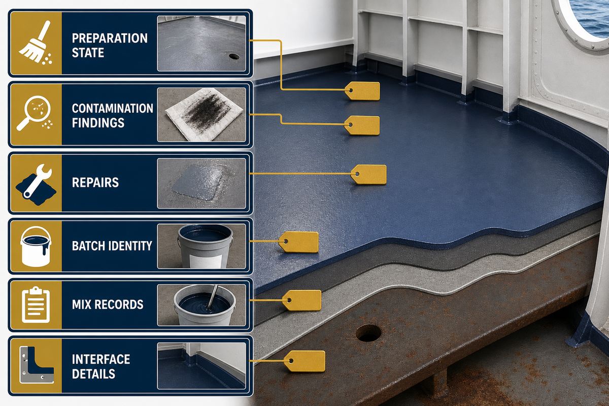
Hidden work inspection should reveal what was installed, where it was installed, on what substrate, what specific recorded conditions, by which process, and who released it. Prioritize evidence that cannot be recreated after the next layer: preparation state, contamination findings, repairs, batch identity, mix records, wet-film or depth checks specified by the project, and interface details.
A reasonable inspection and test plan will distinguish witness, hold, review, and record points. It will also specify the sample locations or the coverage rules, the calibration evidence for the measuring instruments, the acceptance criteria, provisions for what’s considered an acceptable deviation, and who has the authority to release the work. This plan needs to be sourced from project documents. This article can’t establish one inspection frequency for all products and yards.
Do
- Name the exact deck, zone, layer, and interface in every record.
- Record actual readings with units and the specified acceptance source.
- Link deviations, repairs, and reinspection to the original hold point.
- Photograph concealed details with location and orientation references.
Don’t
- Use “checked OK” without the item, criterion, and responsible person.
- Transfer a land-floor limit into a marine job without method review.
- Accept a batch certificate as proof of installed workmanship.
- Close a hidden interface because the visible finish looks uniform.
Concealed conditions can’t always be fully explained by their final appearance. Sounding, moisture investigation, adhesion testing, destructive openings, or other checks may answer bounded questions later, but each brings interpretation limits and possible repair work. That is why an inexpensive release record made at the right moment can be more valuable than an elaborate investigation after completion.
For refit work, add a pre-disturbance review for legacy materials. In the United States shipyard asbestos rule, resilient floor tile, sheet flooring, backing, and mastics are among the materials addressed. This isn’t a removal guide. Use the vessel record, survey, governing requirements, and qualified personnel before cutting, grinding, heating, or lifting an unknown legacy system.
Inspection capsule: if the next action will conceal the substrate, batch, mix, depth, interface, or repair, record it before release. Later tests may investigate a defect, but they cannot recreate the complete preparation and installation history.
7. Diagnose Floor Defects by Competing Mechanisms
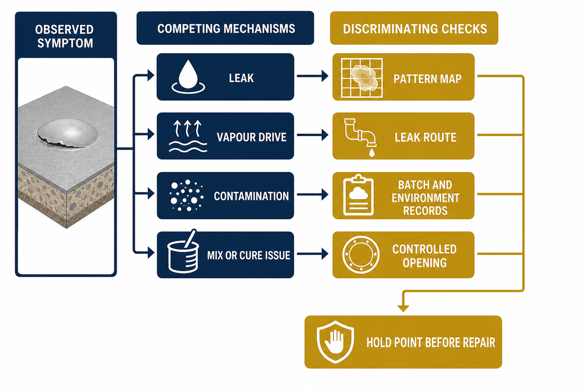
Start a floor investigation with a bounded symptom, preserve the operating and cleaning conditions, map the extent of the symptom, and provide at least two alternative mechanisms. Choose checks or tests that differentiate mechanisms prior to naming a cause. Blisters, cracks, soft areas, staining, noise, and slip reports are symptoms, not causes.
A blister might involve trapped liquid, vapour pressure, contamination, mixing or cure history, or a leak above the floor. A crack might follow deck movement, restraint, impact, a substrate discontinuity, or unsuitable detailing. Similar appearance issues can have multiple causes, and multiple causes can co-exist.
| Observed symptom | Competing mechanisms | Discriminating checks | Hold point |
|---|---|---|---|
| Localized blistering | Leak, vapour drive, contamination, mix or cure issue | Pattern map, leak route, underside context, batch and environment records, controlled opening | Do not seal the surface before the liquid or vapour path is understood |
| Crack at threshold | Movement, rigid bridge, point load, geometry, impact | Detail comparison, movement history, load path, edge exposure, opening if authorized | Do not fill until movement and interface ownership are reviewed |
| Reported slip | Contaminant, cleaning residue, footwear, wear, drainage, surface texture | Incident condition, contaminant, footwear, falls, cleaning method, suitable test context | Do not compare an unrelated dry result with a wet service event |
| Acoustic underperformance | Rigid bridge, wrong path, boundary leak, equipment change, damaged resilient layer | Operating comparison, contact inspection, spectrum or vibration evidence, build records | Do not add floor mass before identifying the controlling path |
| Widespread soft area | Mix ratio, temperature, incompatible material, contamination, premature loading | Batch trace, mixing record, temperature history, hardness map, laboratory review if needed | Quarantine the area and retain samples before removal |
The Health and Safety Executive has concerns about the slip-test method when the real-world contaminant and footwear differ from the test case. That principle applies beyond slip: Choose a diagnostic method which is appropriate to the question, and to the operating state of the service. An answer obtained under the wrong operating state may be both precise and completely irrelevant.
The repair should address the failure cause, not just mitigate a symptom. Record the scope of the failure investigation, the evidence analyzed, the confidence in the cause, the affected extent, the repair description, treatment of adjacent interfaces, cure and protection rules, and scheduled re-inspection. If there’s doubt about the failure cause, label that uncertainty and monitor a defined failure indicator instead of converting a hypothesis into fact.
The diagnosis capsule requires at least two plausible failure mechanisms and one check which can distinguish them, before an extensive repair is warranted. Values from the wrong contaminant, footwear, boundary, or operating state may appear precise but do not answer the service question.
8. Plan Maintenance and Refit from the Accepted Build-Up
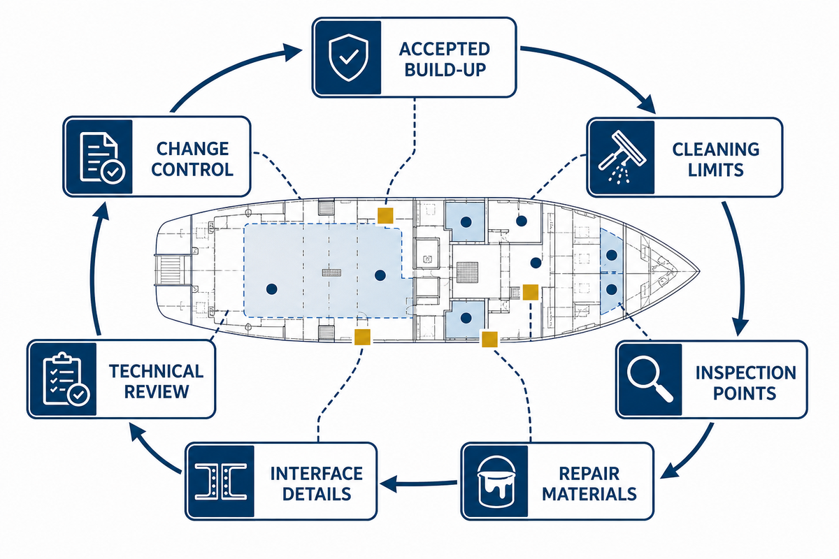
Maintenance begins with the accepted location register, cleaning limits, inspection points, repair materials, and interface details handed over at completion. Operators should know which changes require technical review, because work such as drilling, partitions, equipment feet, wet-area alterations, new cleaning chemicals, or finishing materials may affect hidden layers or boundaries.
Set inspection intervals from service severity, manufacturer instructions, vessel procedures, observed condition, and governing requirements. Don’t assume that one calendar period can be substituted for all the decks on the vessel. A high-traffic food-service route, a dry cabin, an exposed deck, and an equipment foundation create different inspection questions even when they share a product family.
For acoustic construction, a small rigid connection at a perimeter or penetration can change the intended path. For wet spaces, failed sealant, damaged upstands, blocked drainage, or standing water can cause liquids to migrate beneath the finish. For exposed surfaces, changes in wear can affect both cleanability and grip, and repair edges can introduce new interfaces.
Refit scoping should include records and non-destructive observations prior to the destructive phase. Document legacy materials, occupied or adjacent spaces, hot work and dust control boundaries, drainage isolation, removal method, responsibility for repair of the substrate, and how the replacement will fulfill the requirements of the current project. “Like for like” shouldn’t be assessed on appearance alone.
Maintenance capsule: the accepted build-up is the baseline for future change control. Before working on the interface and layer, a new fixing, finish, drain, or partition, as well as a new cleaner or equipment load, should be reviewed.
9. Prepare Handover and RFQ Records That Can Be Audited
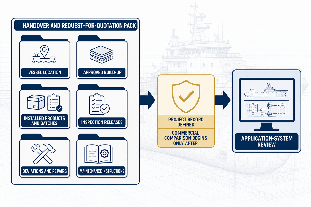
A useful handover pack links each vessel location to the approved build-up, installed products and batches, drawings, evidence passport, inspection releases, deviations, repairs, cleaning limits, maintenance instructions, and responsible contacts. A useful request for quotation supplies the same project inputs before asking a manufacturer to propose a system and gives suppliers the vessel-space schedule with unknowns marked.
Ask them to return a named layer build-up, substrate requirements, interface limits, installation conditions, project evidence map, exclusions, inspection records, repair route, and information required from other trades. Keep commercial price and lead-time comparison separate from technical conformity so an attractive quote does not conceal missing scope.
For a commercial marine flooring product-route overview after the project inputs are defined, use Yibo’s flooring systems by vessel application page. That page owns the application and solution journey. This guide owns terminology, specification inputs, evidence reading, installation control, diagnosis, and handover. The division provides a unique search and buyer task for each URL.
Suzhou Yibo Industry & Trade Co., Ltd. states that it was founded in September 2001, operates a facility of more than 6,000 m² in Suzhou, and produces floating-floor, deck-covering, damping-coating, polyurethane levelling, polyester underlayment, and imitation-teak product families. The company also states that its quality system is certified to ISO 9001:2015 and that relevant products are developed for stated SOLAS and classification-society requirements. Treat every project submission by exact product, current test or approval document, represented assembly, and applicable route rather than extending a company-level statement to an unnamed build-up.
Bring a Defined Floor Package to Technical Review
Prepare the vessel-space schedule, control map, required evidence, and open interfaces. Once this is done, Yibo can provide a response for a defined project package as compared to a generic flooring label.
Handover capsule: an auditable package links location, approved build-up, installed identity, evidence, inspection, deviation, repair, operation, and maintenance. The same structure makes a request for quotation easier to compare without turning an informational guide into a product catalogue.
Related system routes: after the space schedule is frozen, compare the marine acoustic floor systems, primary deck covering, self-levelling deck covering, and marine resin floor systems routes against the project evidence map. These product-route pages support system comparison; this guide retains the project-control and evidence-reading task.
Commercial Marine Flooring Questions from Project Teams
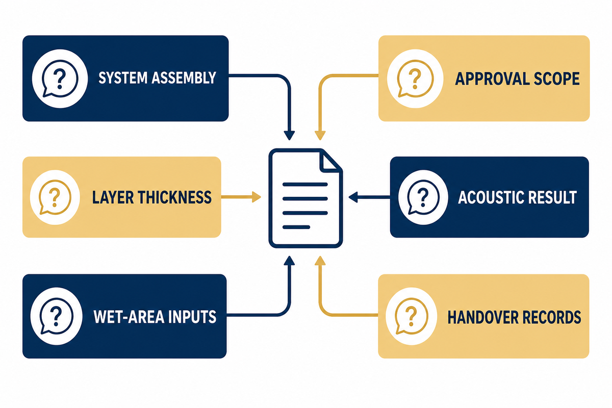
These answers address common issues with the scope of work. They avoid making project decisions. They keep terminology, approval, thickness, acoustic performance, wet-area design, and repair inside their evidence boundaries. Readers can identify the next record or specialist needed rather than copy a value from an unrelated ship.
Is commercial marine flooring one material?
Short answer
No. It’s a project-defined assembly that may include substrate preparation, a primary or levelling layer, resilient or load-spreading elements, adhesives, finish, joints, and interface details. The exact build-up depends on the vessel space, service, evidence, and applicable documents. State each layer’s function and the trade that releases it before construction begins.
Does a classification logo prove that the full installed floor is accepted?
Short answer
No. Check the issuing body, exact product or specimen, layers, substrate, method, intended use, conditions, revision, validity, and vessel-project route. The installed construction may differ from the evidence envelope even when one component name matches. Record the comparison in the Floor Evidence Passport, identify every mismatch, and send unresolved deviations through the project’s approval route before procurement or installation.
What is the correct thickness for a marine floor?
Short answer
There’s no single correct thickness. The specified depth follows geometry, load, layer function, product limits, represented test or approval configuration, interfaces, and installation method. Record which document controls each layer instead of adding the layers into one unexplained total. A levelling depth may vary with deck survey results, while an approval may represent an exact construction. The schedule should therefore show design basis, permitted range, local transition, measurement method, and deviation route separately for each layer.
Can a floating floor guarantee a fixed noise reduction?
Short answer
No. A result belongs to its structure, build-up, boundaries, source, receiving space, and operating condition. Rigid bridges and flanking paths can change it.
What should a wet-area flooring request include?
Short answer
State liquids, temperature, dwell time, cleaning agents, traffic and footwear, falls, drain bodies, upstands, penetrations, adjoining finishes, sanitation criteria, inspection method, and repair access. “Waterproof” or “slip resistant” alone doesn’t define the service condition, the represented test, or the interface details that must remain cleanable; the HSE slip-assessment guidance (https://www.hse.gov.uk/slips/sat/faqsliptests.htm) illustrates why contaminant and footwear must match the question being tested.
Which records matter most after installation?
Short answer
Keep the location register, approved build-up, exact product and batch identity, substrate and environment records, hidden-work releases, interface photos, deviations, repairs, final inspections, cleaning limits, maintenance instructions, and evidence passport. Link each record to a deck, zone, and revision. Add the responsible party, open restrictions, accepted repair materials, and drawings showing drains, thresholds, perimeters, foundations, and penetrations. This lets an operator distinguish an approved change from an undocumented alteration and gives a future shipyard enough context to plan investigation before destructive access.
References & Sources: Scope Boundaries
The sources below pertain to the categories of applicability, measurement, approval, sanitation, refit, and test setting. They don’t approve a Yibo product or select a floor for a particular vessel. Project teams must use current original documents and the governing acceptance route.
- United States Coast Guard: Finishes Source scope: primary deck covering and floor-covering terminology.
- Electronic Code of Federal Regulations: 46 CFR subpart 164.106 Source scope: a current U.S. approval-route example.
- International Maritime Organization: Passenger ships Source scope: passenger-ship convention scope summary.
- International Maritime Organization: Code on Noise Levels on Board Ships Source scope: bounded application, measurement, and survey evidence.
- Applied Acoustics: lightweight floating-floor ship study Source scope: a configuration-specific acoustic case, not a universal claim.
- United States Vessel Sanitation Program: Construction activities: Source scope: plan review and construction-inspection.
- Electronic Code of Federal Regulations: 29 CFR 1915.1001 Source scope: U.S. shipyard asbestos scope, including named resilient flooring materials.
- United Kingdom Health and Safety Executive: slip-assessment questions Source scope: test-setting and service-condition limits.
Editorial method note: Marine Floor Control Map and Floor Evidence Passport are original frameworks created for this article. They aren’t forms issued by the International Maritime Organization, a classification society, or a flag administration.


![Marine PU Floor: Selection & Installation [Guide]](https://yibomarine.com/wp-content/uploads/2026/09/marine-pu-floor-blog-featured-150x150.png)