
Get in touch with Yibo Company


![Marine Damping Coating: Shipyard Guide [2026]](https://yibomarine.com/wp-content/uploads/2026/09/marine-damping-coating-guide-blog-featured.png)
Updated September 2026
Marine Damping Coating is a liquid-applied treatment used to change a ship panel’s vibration and sound-radiation characteristics. At this stage, a sound specification should not start with coating area or film thickness. For this guide, a sound specification must start with the noise source, the path of transmission, the receiving space, the structure that’s moving, and the closing evidence.
This guide is intended for commercial-vessel designers, shipyards, coating teams, acoustic consultants, inspectors, and technical buyers. Here, the purpose is to explain how to determine whether damping is needed in a treatment package, which inputs must be locked, how application records need to be managed, and why a certificate or a material test can’t replace a conducted acoustic acceptance survey.
What Marine Damping Coating Can, and Cannot, Do
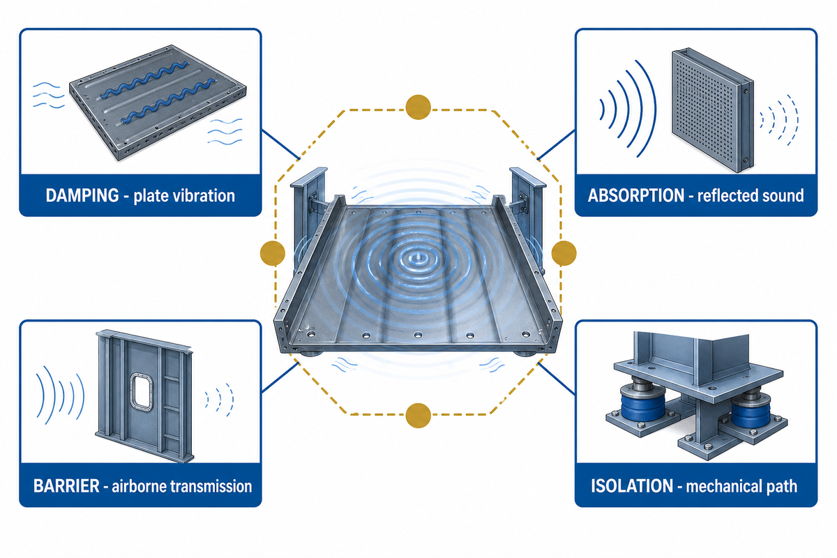
A damping coating dissipates some mechanical energy of a vibrating plate. In addition, when that plate is radiating sound into a compartment, lowering its vibration may also help reduce that airborne radiation. In this context, the treatment isn’t automatically an absorber of reverberant sound, a barrier to sound transmission, a resilient machinery mount, or a cure for a noisy source.
According to the public scope of ASTM E756-05(2023), the method focuses on measuring vibration-damping characteristics, such as the loss factor and modulus. Its usefulness is limited to a frequency range, the material’s useful temperature range, specimen form, and the correct test configuration. In practice, “damping material” describes a function; it does not provide a single room-level result.
That practical distinction also appears in the American Coatings Association’s technical overview: liquid-applied damping is designed for vibrational noise, while airborne transmission and reverberation may require other treatments. Vendor examples provided are more useful for mechanism, not for transferring a product number to a different ship.
Does Sound Deadening Work on Boats?
Sound deadening may work when the treated panel is part of the measured noise path and the damping material is effective in the relevant temperature and frequency range. It will be a disappointment when direct engine noise, exhaust flow, unsealed penetration, rigid machinery connection, or reverberation dominates. Thus, a commercial-vessel decision needs path evidence before material selection.
Do
- Identify the vibrating structure and receiving space.
- Define the frequency, temperature, and measurement endpoint.
- Treat coating as one element of a noise-control package.
Do not
- Use “soundproofing” as a substitute for a path diagnosis.
- Compare unlike decibel figures without their test conditions.
- Assume one coating replaces mounts, barriers, or absorbers.
Follow the Noise Path Before Specifying a Coating
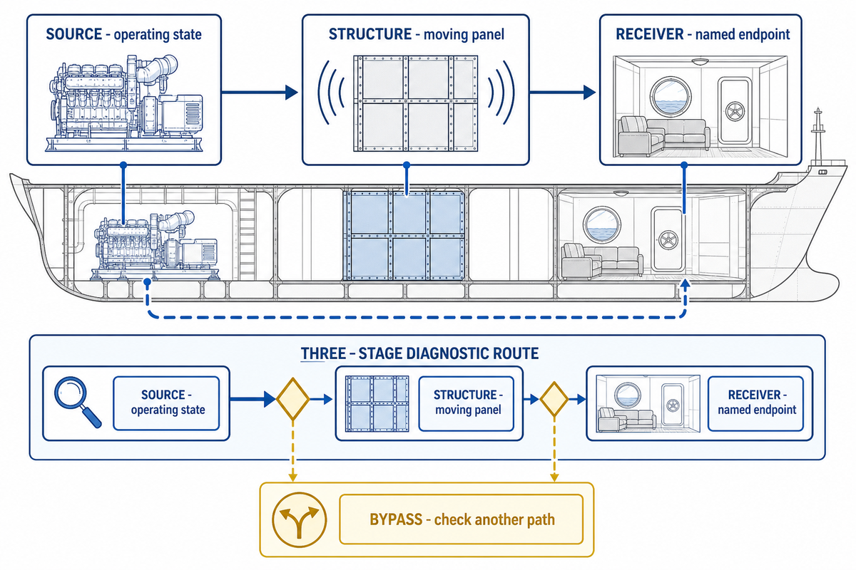
For a defensible treatment decision, a source, structure, receiver statement should be formulated prior to the selection of any material. This statement should define the source of excitation, the structure which is moving or the connection through which motion is transmitted, the location of the reception of sound, and the measurement which shows that the suspected panel is significant. Absent such a statement, a coating may be placed on an accessible surface which isn’t controlling the outcome.
| Layer | Evidence to collect | Question that changes the decision | Stop condition |
|---|---|---|---|
| Source | Machine state, speed/load, exhaust or fluid event, time history | Is the source force itself reducible or isolatable? | Do not coat first when source correction is the controlling action. |
| Structure | Panel vibration, supports, seams, penetrations, plate geometry, boundary condition | Does the suspected plate radiate or transmit the dominant energy? | Stop when the plate is quiet or another rigid path bypasses it. |
| Receiver | Space, microphone position, operating condition, frequency spectrum, acceptance endpoint | Is the concern direct sound, radiated panel sound, reverberation, vibration, or underwater radiation? | Do not reuse a result measured for a different endpoint. |
According to the International Maritime Organization ship-noise overview, on-board noise rules are distinct from underwater-radiated-noise guidance. This distinction is important. Accommodation noise, exposure of personnel to noise, local plate vibration, laboratory treatment performance, and underwater radiation won’t have a single instrument or a single acceptance criterion.
Consider a simple field example. Vibrating bulkheads beside machinery may radiate sound into adjacent accommodation. Damping that plate may help, especially when a lightweight panel is easy to excite. If a rigid pipe support carries the main vibration around the treated panel, or if the dominant sound enters through an open ventilation path, the same coating can be applied and still fail to move the room reading enough.
Match Treatment Type to the Structure and Frequency Problem
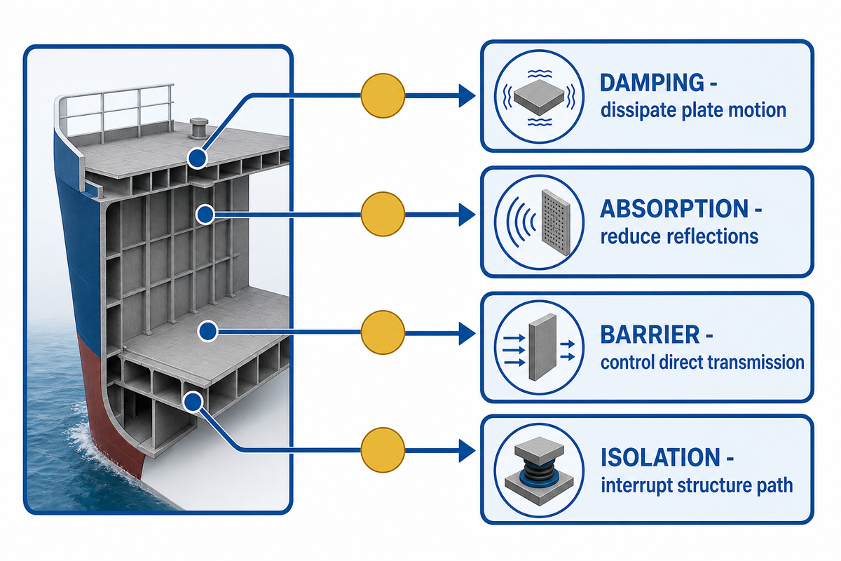
Where sound reduction is concerned, treatment families should be compared by function rather than by a single sound reduction label. ASTM E2963-24 separates transmission loss, radiation efficiency, acceptance, absorption, and damping when evaluating ship bulkhead, deck, and side-shell treatments. One system may influence more than one factor, but the test result must identify which factor was actually measured. Materials that dampen panel motion therefore cannot be ranked against absorbers or barriers without first naming the measured factor.
| Treatment family | Primary function | Good fit when | Not a complete answer when |
|---|---|---|---|
| Liquid-applied damping | Dissipates plate vibration | Complex geometry, seams, and access favor spray or trowel application | Direct airborne or bypass transmission dominates |
| Free-layer sheet | Adds viscoelastic damping to a panel | Flat surfaces and controlled bonding suit cut sheets | Irregular details or fire/adhesive boundaries remain unresolved |
| Constrained-layer treatment | Shears a viscoelastic layer between structural faces | The construction can accept a bonded constraining layer | Weldability, geometry, repair access, or weight rules conflict |
| Porous absorber | Reduces reflected sound in a space or enclosure | Reverberation and exposed-surface absorption matter | A vibrating plate or rigid support carries the main energy |
| Barrier or enclosure | Reduces direct airborne transmission | Mass, continuity, sealed penetrations, and ventilation are controlled | Structure-borne vibration bypasses the barrier |
| Resilient mount or floating floor | Interrupts mechanical transmission | Equipment or deck build-up can be isolated from the receiving structure | Bridges, penetrations, or rigid services short-circuit the resilient layer |
For broader build-up decisions, Yibo’s marine acoustic floor systems overview places damping in the larger floor and deck context. A marine floating floor addresses a different part of the path and shouldn’t be treated as a synonym for a damping layer.
The ASTM E2963-24 public scope is especially useful here: it names the construction and measured factor, and it also says marine-division materials must meet the applicable non-acoustic requirements. Acoustic effectiveness and suitability for installation are related decisions, not interchangeable certificates.
Define Project Inputs with the 6-Field Workfront Condition Passport
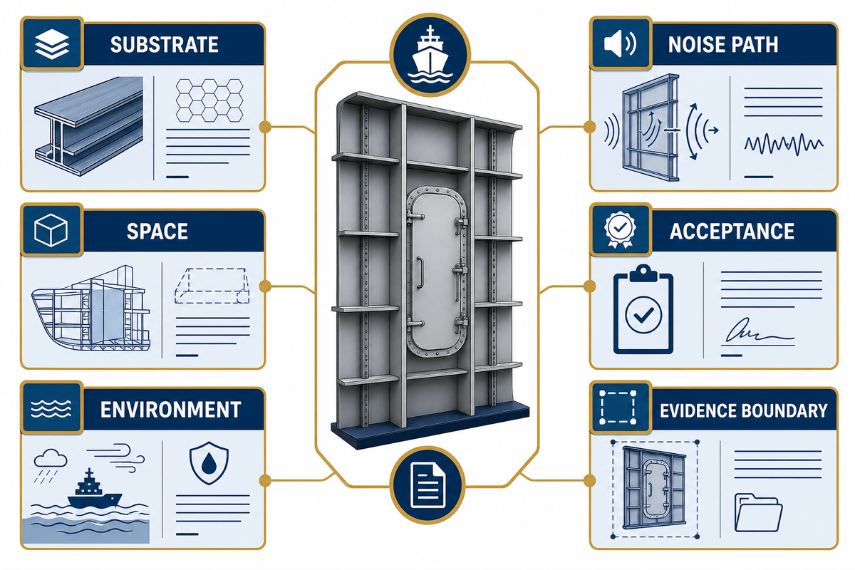
A supplier or consultant can’t address the sizing of a damping treatment based on square meters solely. At minimum, the brief is a six-field record summarizing substrate, vessel space, environment, noise path, acceptance method, and evidence boundary. Where a field is unknown, the response should explicitly state the missing evidence rather than hiding it in an allowance factor.
- Substrate: where known steel or aluminum grade, plate thickness, geometry, stiffeners, welds, existing primer or coating, corrosion, damage, and access side.
- Space: machinery space, accommodation, control room, workshop, deck zone, enclosure, or other receiving area.
- Environment: application and service temperature, moisture, condensation, salt contamination, fluids, abrasion, cleaning, and adjacent work.
- Noise path: source state, suspected vibrating structure, rigid bypasses, receiving position, and frequency evidence.
- Acceptance: identified material property, panel vibration, laboratory treatment result, room noise, comfort notation, or other named endpoint and method.
- Evidence boundary: mandatory fire, classification, flag, project, quality, product, installer, and acoustic records, each with issuer and scope.
How Much Sound Deadening Do I Need for a Boat?
Area alone won’t suffice to answer the question for a commercial vessel. Treatment zones and an approved dry-build target for the named system are required, along with allowances governed by surface profile, geometry, access, application method, waste policy, and required repairs. It’s necessary to also demonstrate that acoustic fit is achieved, and consuming the planned quantity won’t be acceptance evidence.
Consider an engine-room boundary with an aluminum panel, an existing primer, limited rear access, and an accommodation-space target. Before a material amount can be requested, the panel thickness and supports, primer compatibility, surface condition, service temperature, frequency evidence, application method, dry-build instruction, and acceptance survey are required. These six fields allow the dependencies to be shown.
The vessel-area context can be managed through the marine flooring applications map. That page provides some information on the space and duty, but it can’t replace the workfront passport or select acoustic treatment.
Prepare Steel and Aluminum Substrates for Application
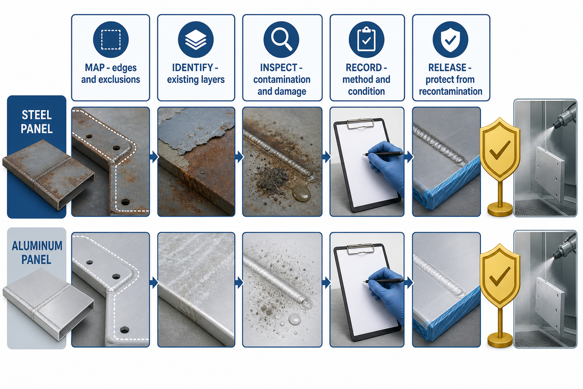
Preparation should release a specific substrate for a specific approved system. The release needs to cover cleanliness, profile, residual salts or contaminants, dryness, existing layers, welds and edges, primer compatibility, access, and the status of adjacent work. General abrasive-blast advice can’t substitute the coating data sheet or the shipyard specification.
- Map the treatment boundary and show penetrations, stiffeners, edges, repairs, shadow areas, and surfaces that must not be coated.
- Identify every existing layer. Determine if it stays, if it gets removed, or if it needs a compatible tie or primer layer within the approved system.
- Inspect for corrosion, weld spatter, sharp edges, damage, moisture, dust, oil, grease, and soluble contamination as required by the project.
- Record the preparation method, the resulting condition, the instrument used for inspection, the date, zone, and the person who released the preparation.
- Protect the released surface from recontamination and define the maximum allowed delay or recheck condition before application.
Potential causes of adhesion problems and defective cures include salt, moisture, oil, dust, poor surface profile, and a retained layer that isn’t compatible. The correct statement isn’t “all steel must receive one preparation grade”; it’s “the actual steel or aluminum condition must meet the approved system and project requirement before release.”
Safety stop: Surface preparation and coating work can interact with confined-space controls, ventilation, atmosphere testing, respiratory protection, ignition control, electrical grounding, and hot work. Use the current safety data sheet, work permit, shipyard rules, and competent-person decisions. This guide is not a work authorization.
For employment at shipyards in the United States, 29 CFR 1915.35 on painting provides controls for ventilation, respirators, flammable materials, bonding, grounding, and gas-free conditions. Other jurisdictions and projects have their own controlling rules; this citation is an example for that authority, not a universal work-control instruction.
Control Mixing, Spray Technique, Film Build, and Cure
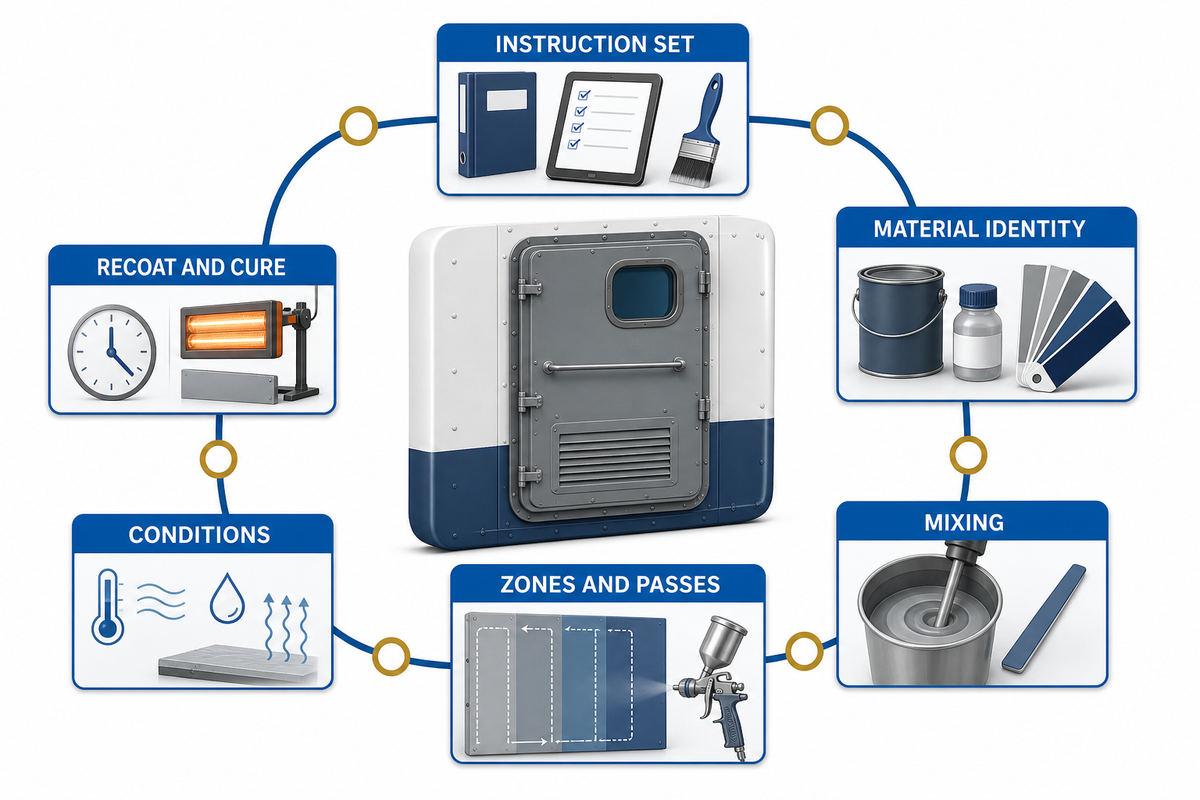
Application is one connected envelope. Material condition, batch identity, mixing, equipment, hose and nozzle setup, pass build, access, temperature, humidity, ventilation, recoat interval, cure and zone identity can affect the finished film. However, a total quantity and one final average can’t prove that the variables remained controlled.
- Freeze the instruction set. Use the current approved product data, safety data, primer/interface instructions, project specification, and accepted procedure.
- Verify material identity. Record component, batch, shelf status, storage condition, and conditioning needed before use.
- Control mixing. Follow the named ratio, sequence, equipment, induction rule, usable time, and limits on dilution or additives. Don’t transfer a mixing ratio from another product family.
- Define zones and passes. Assign each work front a unique identity, and document how each pass or layer builds toward the approved goal.
- Monitor conditions. Record the condition of both the environment and the substrate at the frequency specified by the project, and document changes that were observed during a shift.
- Respect recoat and cure boundaries. Hold the next operation; don’t release it until the specified condition is satisfied, because clock time alone isn’t enough when temperature, humidity, or other variables change.
ASTM E756 instructs laboratories to follow material application directions and allow adequate cure before assessing the specimen. In its current public scope, ASTM E756-05(2023) defines a laboratory method for measuring vibration-damping properties; it does not select a shipboard coating system. That rule is modest but important. Even a controlled beam test can be perturbed by application or cure. In service, a ship installation adds more geometry, access, environmental, and handover variables.
More thickness isn’t a universal recovery action. Too little build can leave an incomplete system; too much can create cure, cracking, or other product-limit problems. Acoustic response also depends on the plate and the material’s frequency- and temperature-dependent behavior. For an out-of-range reading, the correct response is the approved repair procedure, not an improvised extra coat.
Application teams must maintain separate safety and quality records and cross-reference the same zone and time window. Passing a wet-film reading doesn’t prove adequate ventilation, and a safe-atmosphere release doesn’t prove mixing or film build. Each of these is required when their respective rules apply.
Inspect the System with the Film-Build Variance Map
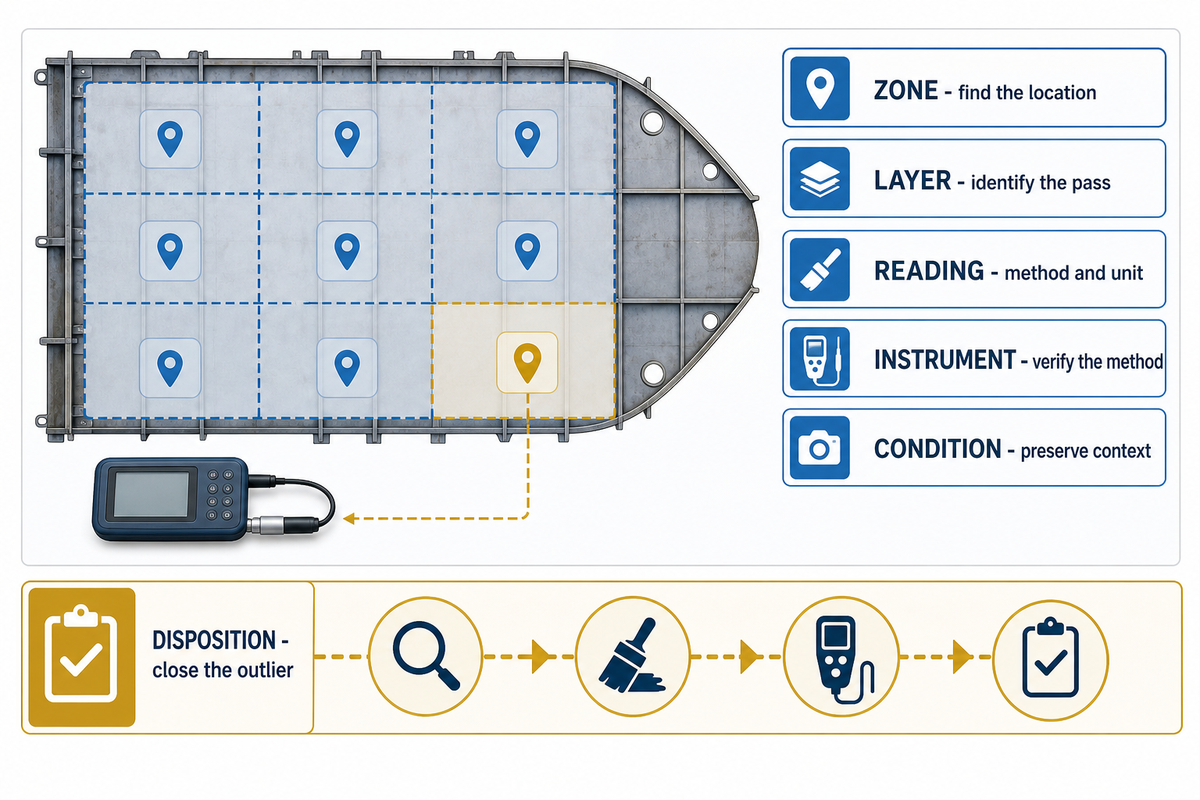
To understand the readings, you need to know where they came from, which layer or pass they represent, and what conditions influenced them. An average value can mask thinned edges, heavy bays, inaccessible shadow zones, repairs, or a change of batches. The Film-Build Variance Map transforms a list of readings into traceable workfront evidence.
| Trace field | What to preserve | Why an average is insufficient |
|---|---|---|
| Zone and location | Frame, bay, side, elevation, grid, or marked drawing reference | The reading must be findable for repair and recheck. |
| Layer or pass | Named layer, pass number, and interface status | A final total can hide which stage created the variance. |
| Reading | Wet or dry method, value, unit, and acceptance range | Wet and dry figures answer different process questions. |
| Instrument | Instrument identity, verification or calibration status, and method limits | The result is not stronger than the method used to obtain it. |
| Condition | Time, batch, surface and ambient readings, cure state | A changed condition may explain a local pattern. |
| Disposition | Accept, investigate, repair, remeasure, and close with authority | An outlier should not disappear into the arithmetic. |
Illustrative record only: The sample below is a fictional training dataset showing how local variation remains visible. Its values aren’t product limits, target film builds, cure instructions, or acceptance criteria. In real work, the map must use the approved system documents and project inspection plan.
| Record type | Dry reading | Ambient record | Surface record | Disposition |
|---|---|---|---|---|
| Grid A1 | 1.20 mm | 23 °C / 55% RH | 21 °C | Compare with the approved range. |
| Grid A2 | 1.15 mm | 23 °C / 55% RH | 21 °C | Compare with the approved range. |
| Grid A3 | 0.82 mm | 24 °C / 57% RH | 22 °C | Flag the local low pattern for review. |
| Grid B1 | 1.18 mm | 24 °C / 57% RH | 22 °C | Compare with the approved range. |
| Grid B2 | 1.22 mm | 24 °C / 58% RH | 22 °C | Compare with the approved range. |
| Grid B3 | 0.79 mm | 25 °C / 60% RH | 23 °C | Check access or pass history in this zone. |
| Grid C1 | 1.19 mm | 25 °C / 60% RH | 23 °C | Compare with the approved range. |
| Grid C2 | 1.17 mm | 25 °C / 61% RH | 23 °C | Compare with the approved range. |
| Grid C3 | 1.21 mm | 25 °C / 61% RH | 23 °C | Compare with the approved range. |
A film-build map doesn’t define an acceptance range, which must come from the approved product/system instructions and the project plan. Nor does a film-build map prove an acoustic outcome. For that reason, the ASTM E2963-24 scope must remain separate from inspection evidence: it addresses the laboratory acoustical effectiveness of ship noise treatments. It proves how the treatment was installed, which is one factor in assessing the survey outcome.
Minimum Inspection Handover
A useful handover includes the released substrate, material batches, mixing or preparation events, environmental conditions, mapped passes, wet and dry readings, cure release, repairs, exceptions, and the sign-off authority. Attach a drawing or photograph only when the location and date are identified. An unreferenced photograph is an illustration, not a trace record.
Diagnose Weak Results Without Blaming the Material First
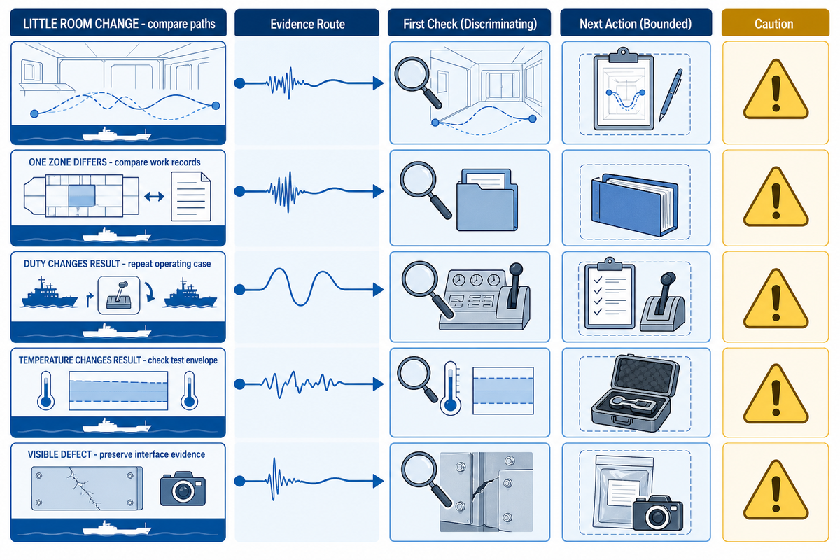
A weak reading or a disappointing perceptual finding is a diagnostic problem, not immediate proof of a defective material. The shortest reliable investigation compares the current test to the baseline, preserves the operating state and frequency data, checks if the treated panel is still in the dominant path, and reviews application and cure records by zone.
| Observed symptom | Discriminating check | Bounded next action |
|---|---|---|
| Room result changed little | Compare source state, spectrum, direct paths, penetrations, and panel vibration | Correct the path model before changing treatment. |
| One zone performs differently | Compare substrate, batch, pass, build, environment, cure, and repairs | Isolate the variance and follow the approved repair route. |
| Result changes with duty | Repeat the source and receiver condition, then compare frequency content | Define separate operating cases instead of averaging them. |
| Result changes with temperature | Check material test envelope and actual panel temperature | Reassess suitability within the named temperature/frequency window. |
| Appearance defect is present | Preserve interface, contamination, preparation, mix, build, and cure evidence | Do not assign cause from appearance alone; obtain authorized technical review. |
The United States Occupational Safety and Health Administration technical manual on noise control distinguishes source control, vibration damping, isolation, absorption, and barriers. The examples are general industrial guidance, not marine product instructions, but the function-first logic is directly useful for avoiding the wrong corrective action.
A pre-treatment and post-treatment comparison should preserve the same measurement endpoint and a comparable source state. If those conditions differ, the measured difference combines treatment effect with measuring variation. It’s better to report the discrepancy than to draw inferences about the performance from disparate evidence.
Build the Acoustic Evidence Question Tree for Handover
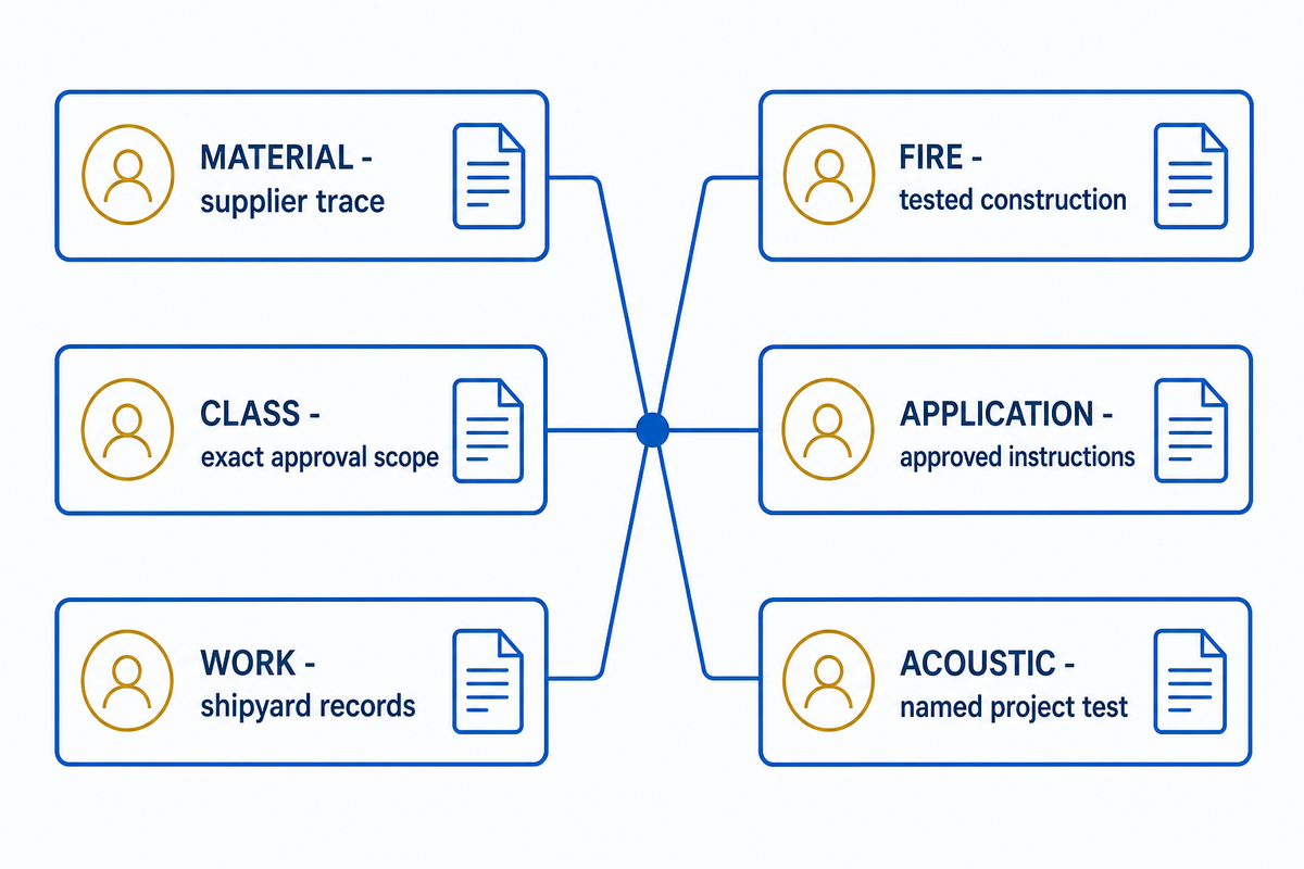
Each document in the handover should answer a specified question. For a document-by-document handover screen, use Yibo’s classification documentation and test-part checklist after the project evidence owner has been defined. A quality-system certificate states something about the management system; a fire document defines the scope of the construction and test; a classification record states the issuer’s approval scope; a product data sheet controls the use of the product; an application record describes the work; and an acoustic report records a measured end point.
| Question | Evidence owner or issuer | What it may establish | What it does not prove |
|---|---|---|---|
| What material was supplied? | Manufacturer/supplier and trace records | Identity, batch, stated product properties | Correct installation or field acoustic result |
| What construction was fire tested? | Test laboratory and approving authority | Named assembly, method, result, and limits | Loss factor or ship-space noise result |
| What does class accept? | Classification society and certificate holder | The certificate’s exact product, plant, assembly, and validity scope | Any use outside that scope |
| How should it be applied? | Approved system instructions and project procedure | Preparation, mixing, build, recoat, cure, and repair envelope | That the field work followed the envelope |
| How was the work executed? | Shipyard, applicator, inspector, and workfront records | Zone-level process and inspection traceability | The required acoustic endpoint |
| Did the treatment meet the acoustic target? | Qualified test party under the project method | Named endpoint, condition, locations, result, and uncertainty | Other noise endpoints or certificate scopes |
The company states Suzhou Yibo Industry & Trade Co., Ltd. as an ISO 9001:2015-certified manufacturer with a marine floor portfolio that includes damping coatings, floating floors, deck coverings, resin floors, and related systems. Those are company-attributed facts. It also states that the company was founded in September 2001 and that its Suzhou site covers more than 6,000 m². A buyer should still read the current certificate holder, issuing body, validity, covered site, product/assembly identity, and project applicability before relying on any record.
The International Maritime Organization Code on Noise Levels on Board Ships provides the formal on-board framework. It doesn’t identify one universal damping product, and citing the Code can’t close film build, fire scope, classification acceptance, or a project survey without the corresponding evidence.
Evidence records what was measured. Project acceptance must still match the installed result and the named endpoint.
Where Rules and Trends End, and Project Evidence Begins
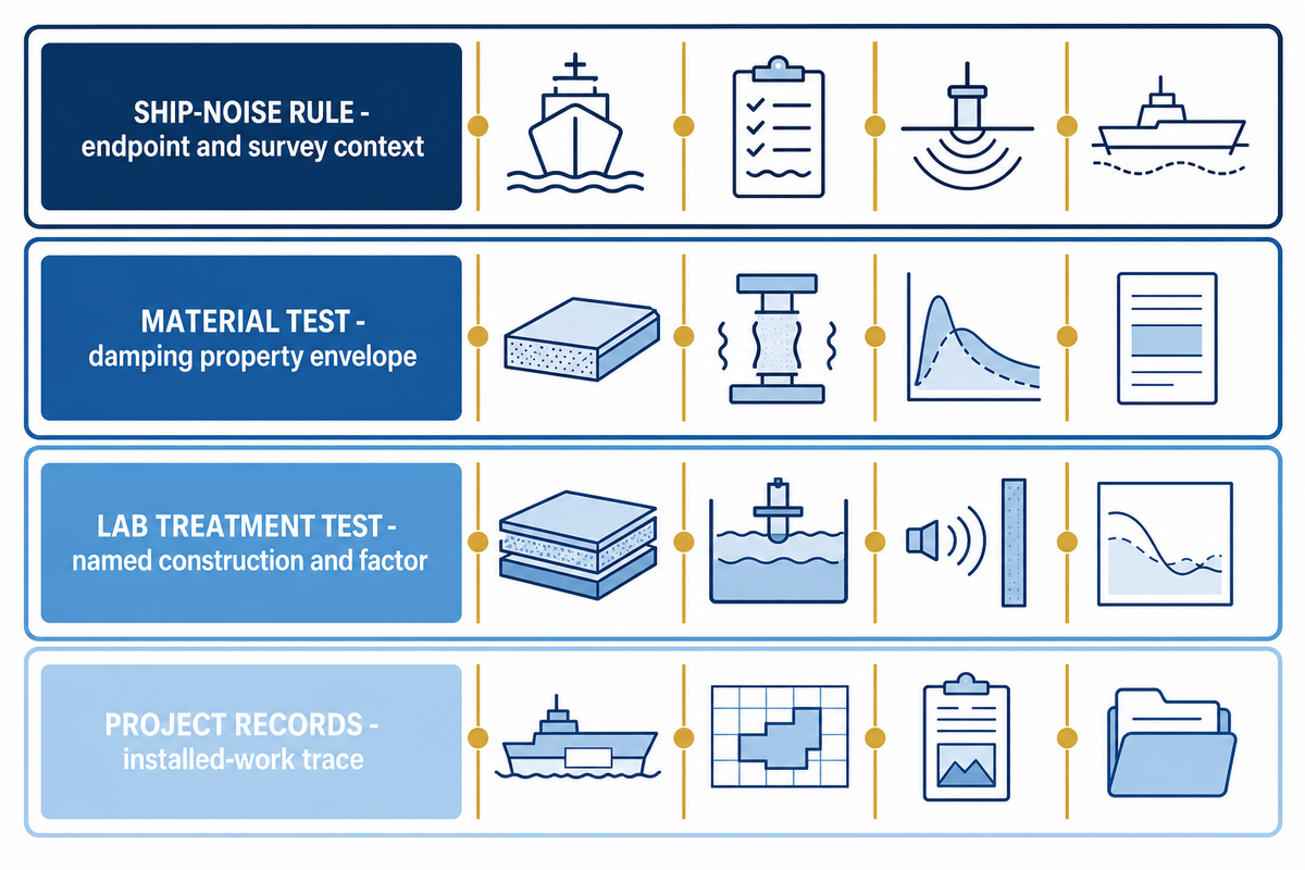
Current rules and active test methods define terminology, scope, and measurement structure. They don’t convert a material name to a field result. For example, ASTM E756-05(2023) defines a vibration-damping property method, not a universal shipboard product choice. By September 2026, the durable planning signal isn’t a market forecast; it’s the continued need to differentiate on-board noise, underwater-radiated noise, material damping properties, laboratory ship-treatment effectiveness, and the project’s own acceptance method.
| Reference | Establishes | Does not establish |
|---|---|---|
| Ship-noise rule or notation | Applicable space, vessel, endpoint, limit, and survey context | One required coating or universal build |
| ASTM E756 | Material damping property method and test envelope | Room result on a completed vessel |
| ASTM E2963 | Laboratory effectiveness of named ship treatments and factors | Automatic approval for every installation |
| Product and project records | Approved use envelope and actual workfront trace | Acoustic acceptance unless the named test was completed |
The forecast pages found during research weren’t used to support market size or market growth assumptions because the methods and source data on which they were based weren’t transparent enough. This is intentional. A shipyard will gain more value from the current standard, exact product instructions, and repeatable acceptance plan than from a loosely sourced demand forecast.
Put the Guide to Work Before Product Selection

Four things must be carried into any commercial review: a source, structure, receiver path statement, the six-field workfront passport, the proposed acceptance method, and the evidence question tree. These bring a supplier the ability to identify what’s missing and discuss a compatible system without pretending that area or thickness alone provides the answer.
To begin, locate Yibo’s marine damping coating system options. Once those inputs are defined, review the product-specific information, configuration, current evidence, and project-fit discussion there. That solution page is responsible for the commercial decision; this guide is the diagnostic and control reference.
Field takeaway
Specify the noise path before the coating, bind every performance number to its test envelope, control work by zone and layer, and close each question with the document or measurement that actually owns it.
Discuss Your marine damping Workfront.
Marine Damping Coating FAQs
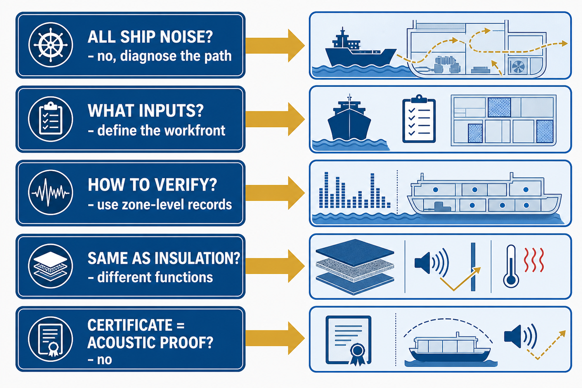
Does a damping coating reduce all types of ship noise?
A damping coating reduces vibration-related radiation only when the treated structure is part of the controlling noise path. It does not replace source, barrier, absorption, or isolation controls.
A damping coating can reduce vibration in a plate and the sound that plate radiates. It doesn’t automatically reduce direct machinery noise, exhaust or airflow noise, reverberation, transmission through openings, or structure-borne energy bypassing the panel. Define the source, path, receiver, frequency range, and operating state before deciding that damping is the right treatment. That boundary follows the Occupational Safety and Health Administration Technical Manual’s distinction among vibration damping, source control, barriers, absorption, and isolation; it is not a marine product approval.
What information is needed before selecting a marine damping coating?
Selection requires a defined substrate, vessel space, environment, noise path, acceptance method, and evidence boundary. A workfront brief must also identify unknown inputs instead of hiding them.
The supplier should receive panel material and thickness, geometry and supports, existing coating condition, treatment side and access, application and service environment, noise source and receiver data, relevant frequency evidence, mapped area, required acoustic endpoint, and required fire, classification, flag, product, and quality records. Unknown inputs should be listed rather than replaced by a generic coverage allowance.
How should a shipyard verify damping coating application?
Application verification needs zone-level preparation, material, mixing, condition, pass, film-build, cure, repair, and release records. The acoustic endpoint still needs its own named project test.
Map readings to stable zone and layer identifiers, record the method and unit, preserve instrument status, and compare each result with the approved system and project criteria. Record outliers and their disposition instead of hiding them in an average. Application evidence confirms the work process; a separate acoustic test is still needed when the project requires an acoustic outcome.
Is a damping coating the same as sound insulation?
Damping and sound insulation are different functions, although both may appear in one ship treatment assembly. They must be matched to the actual transmission path and acceptance endpoint.
No. Damping controls structural vibration; insulation, absorption, barriers, and resilient isolation address different transmission mechanisms.
Does a fire or classification approval prove acoustic performance?
A fire or classification approval proves only the product or assembly, method, holder, site, and scope stated in that record. Acoustic acceptance requires its own named test and result.
An acoustic claim needs its own test method, specimen or construction, temperature, frequency, measured factor, and result. A quality-system certificate addresses the management system; a fire report addresses the tested construction; classification documentation addresses its named approval scope; and shipyard records address the installed work. None should be substituted for a room survey, vibration measurement, or laboratory acoustic test that it doesn’t contain.
References & Sources
- ASTM E756-05(2023): Measuring Vibration-Damping Properties of Materials ASTM International
- ASTM E2963-24: Acoustical Effectiveness of Ship Noise Treatments ASTM International
- Ship Noise Overview International Maritime Organization
- Code on Noise Levels on Board Ships, Resolution MSC.337(91) International Maritime Organization
- 29 CFR 1915.35: Painting Occupational Safety and Health Administration
- OSHA Technical Manual: Noise Occupational Safety and Health Administration
- Sound Damping Coatings Make a Real Impact American Coatings Association
Why This Guide Uses Evidence Boundaries
Suzhou Yibo Industry & Trade Co., Ltd. supplies marine floor and acoustic-system products, including damping coatings. This article deliberately separates structural damping, airborne control, application quality, certificate scope, and project acceptance so shipyard teams can ask for the right evidence before selecting a system. Product-specific claims and approvals belong to the relevant current technical and approval records, not to a generic guide.



![Marine PU Floor: Selection & Installation [Guide]](https://yibomarine.com/wp-content/uploads/2026/09/marine-pu-floor-blog-featured-150x150.png)