
Get in touch with Yibo Company


Updated September 2026
Marine resin floor systems are coordinated floor build-ups for defined vessel spaces, steel-deck conditions, service environments and acceptance routes. Beyond resin, the completed system is determined by many factors including the preparation and primers, intermediate layers, textured finishes and aggregates, top coats, joints, drains, penetrations, controls for the environment, and documentation of the process while the work is in progress.
Resin flooring systems used in the marine sector can be found on ship and offshore platform projects, though it can’t be assumed that one flooring system will accommodate all the requirements of a given space. In the end, the desired function of the vessel and documented construction will dictate the selection of the flooring system.
This guide gives project teams a method for framing the duty, comparing complete systems, witnessing hidden work and preserving repair evidence. Product models, specifications, certificate scope and quotation belong on Yibo’s separate solution page.
Marine resin floor systems are selected as complete, location-specific build-ups. The project must match exposure, access, substrate, interfaces, layer sequence and evidence scope before installation, then connect hidden-work records to final vessel acceptance.
Quick Specs: inputs to freeze before selection
- Vessel, compartment, flag or Administration and work classification
- Steel deck, retained coating, movement and every service interface
- Water, chemical, traffic, cleaning, temperature and application exposure
- Layer schedule, current product instructions, approval route and witness plan
Formatting example only: a training form might show 12 m² of deck, a 7 mm plate, a 5 mm layer, a 2 m perimeter, 18°C, 65% relative humidity, a 10-minute mix, 30-minute application, 12-hour recoat check, 24-hour foot-traffic check, 48-hour equipment check, 7-day observation, a 250 kg trolley and a 5 L cleaning batch. None of these hypothetical examples defines a product limitation or a project recommendation.
Key points
- A resin-family name can’t prove the concealed construction.
- Application safety and finished-floor service exposure need separate controls.
- A certificate remains bound to its stated assembly and approval scope.
- Hidden-layer records should be planned before the next layer covers the evidence.
A Marine Resin Floor Is a Build-Up, Not a Chemistry Label
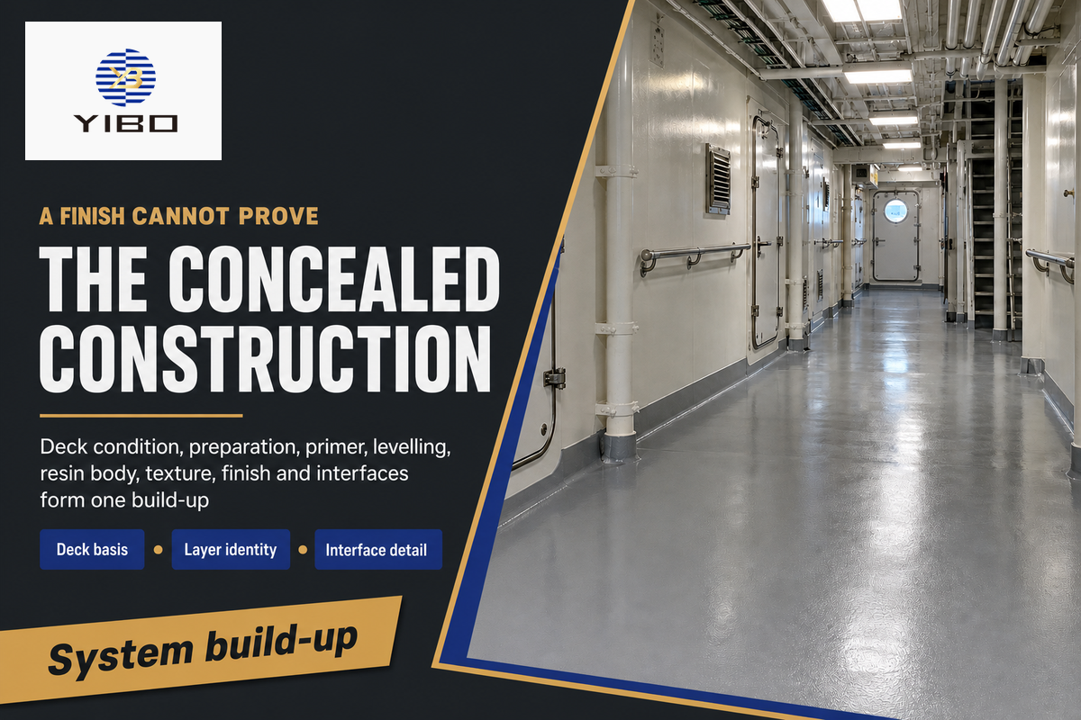
A marine resin floor is the total system built between a prepared structural deck and an exposed service finish. Being called epoxy or polyurethane doesn’t identify the substrate condition, primer, levelling layer, resin body, aggregate, topcoat or edge detail. Each component must have both a function and a position in the approved system that’s documented.
Things that look the same can cover different primers, the order of layers, reinforcement, texturing and attachment details. Having a glossy surface doesn’t assure deck preparation, fire-test scope, or that a drain or a penetration has been correctly installed. Looks can’t reconstruct hidden work below the surface.
Start your specification with a layer schedule. Identify the steel deck and any coating that’s retained, the preparation and cleanliness requirement, primer or adhesion layer, levelling, smoothing or primary deck covering, resin body, broadcast or texture component, seal or topcoat, covings, joints, drains, thresholds and penetrations. Identify which components form part of the tested or approved construction and which are project-specific details.
Evidence capsule: A sample record might identify an 8 mm steel plate, a 24 m² compartment, a 6 mm transition and an 18°C workfront. Those figures only demonstrate record structure. The actual values must come from the approved drawing, current product instructions and project procedure.
Use the Exposure–Access–Evidence Ledger: a 3-Side Open-Input Register
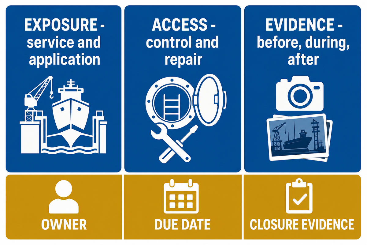
The Exposure–Access–Evidence Ledger is the primary project-handoff tool of this guide. It isn’t a classification society rule. Exposure describes the characteristics of the service floor and the conditions during its application. Access describes whether the work can be controlled and if it can be repaired. Evidence describes the requirements of the project that must be satisfied before, during and after completion of installation. Sufficient records address all three elements by assigning unresolved items an owner, due date and closure evidence before product comparison.
| Exposure category | Exposure input | Access input | Evidence needed | Closure decision if unresolved |
|---|---|---|---|---|
| Water and wet cleaning | Source, frequency and drainage route | Drying window and isolation area | Cleaning plan and drain detail | Do not select texture by label |
| Oils, fuels or chemicals | Named substance, concentration and contact | Spill response and repair access | Product-specific compatibility evidence | Request the missing exposure data |
| Temperature | Service range and local heat source | Conditioning and monitoring | Applicable product and project limits | Hold the workfront |
| Traffic and impact | People, trolleys, wheels and dropped loads | Route closure and patch access | Load schedule and service-area map | Define duty before comparison |
| Deck movement | Joints, vibration and structural change | Joint preparation and later inspection | Coordinated structural and floor details | Escalate the interface |
| Ultraviolet exposure | Interior, exterior or intermittent exposure | Weather window and protection | Finish-specific exposure statement | Separate colour from service proof |
| Application atmosphere | Uncured materials, vapours and ignition sources | Ventilation, exclusion and atmosphere checks | Safety data and jurisdictional procedure | No application without controls |
| Return to use | Foot traffic, equipment and wet cleaning | Available shutdown | Separate readiness criteria | Revise sequence or system |
| Approval route | Vessel, space, flag and voyage | Review and witness availability | Current record and installed-scope match | Refer to the governing party |
| Future repair | Likely damage and contamination | Opening, edge and recoat access | Repair procedure and retained records | Design the repair boundary now |
Finished-floor chemical resistance doesn’t provide safety while working with liquid materials that are being mixed or applied. As illustrated by United States rule 29 CFR 1915.35, in some cases, ventilation, the use of respiratory protection, vapour testing, ignition control, and a decision to make the work area gas-free can be separate functions. Current material safety information, yard procedure and jurisdiction must define the actual controls.
Key takeaway
A system is not ready for selection when the workfront cannot support its environmental, safety, timing or witness requirements. Access is part of suitability. Use Yibo’s match compartment duties to vessel spaces resource to organize compartment context before requesting a system configuration.
Epoxy or Polyurethane: Compare the Complete System
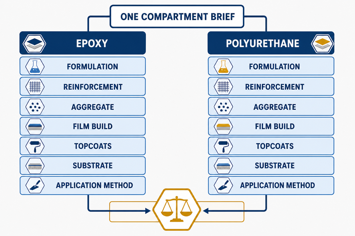
Classifying epoxy and polyurethane systems is a good starting point, although neither can be considered the best for all vessel cases. Variables such as formulation, reinforcement, aggregate, film build, topcoats, substrates, exposure and method of application can affect the final result within either family. Evaluate the proposed systems for one compartment brief and ask the supplier to bind every answer to the named build-up.
| Dimension | What to compare | Evidence object | Unsafe shortcut |
|---|---|---|---|
| Substrate relationship | Preparation, retained coating and primer | Approved instruction and deck release | “Bonds to steel” without condition |
| Movement and impact | Actual structural and traffic duty | Project-specific selection statement | “Flexible” or “hard” as sufficient proof |
| Chemical contact | Named chemical, concentration, time and temperature | Formulation-specific compatibility data | Generic “chemical resistant” claim |
| Wet traction | Texture, contaminant, footwear and cleaning | Relevant method and stated condition | “Anti-slip” without test scope |
| Layer compatibility | Primer, body, broadcast and topcoat | One controlled system schedule | Mixing unrelated product claims |
| Workfront fit | Mixing, application and recoat windows | Current product instruction and method | One universal cure time |
| Approval scope | Tested construction and permitted variations | Current certificate and supporting record | Brand or chemistry equals approval |
| Repairability | Patch edge, recoat compatibility and colour expectation | Repair procedure and mock-up where needed | Invisible patch assumed |
| Maintenance duty | Soil, detergent, tools and inspection | Cleaning and maintenance plan | Chemistry predicts service life |
| Handover proof | Batch, location, witness and acceptance linkage | Location-indexed dossier | Brochures as as-built evidence |
Sherwin-Williams classifies coatings, slurries, and mortars as separate construction types. Their general-purpose thickness bands aren’t marine specifications. “Durable”, “suitable”, or “decorative” can’t substitute the named assembly, duty, and evidence.
“Performance depends on many factors: surface preparation, application method and its quality, coating chemistry, film thickness…”
Most of Schoff’s discussion is on maintenance coatings and not vessel floors. The scoped point still holds: Chemistry alone can’t predict an installed result. Marine projects must define the contaminant, cleaning method, footwear, drainage and relevant test condition before accepting an “anti-slip” coating claim.
Separate Layer Category, Test Evidence and Vessel Acceptance
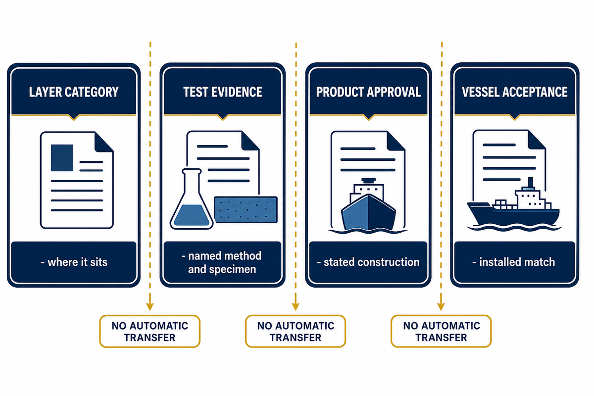
Material category, laboratory evidence, product approval, and vessel acceptance address different issues. Floors may incorporate a primary deck covering, a finish or both, while a certificate can apply only to the construction it names. Final acceptance still depends on the vessel, compartment, flag or Administration, voyage, project conditions and the installed match to reviewed documents.
| Evidence object | Can establish | Cannot establish alone | Read-back fields |
|---|---|---|---|
| Product data sheet | Stated product properties and instructions | That the named product reached the compartment | Product, revision and limitations |
| Safety data sheet | Hazards and handling information for the material | Finished-floor service suitability | Product identity and revision |
| Test report | Named specimen under a stated method | Performance of an altered build-up | Specimen, substrate, method and result |
| Type-approval certificate | Holder, product or construction, basis and limits | Automatic acceptance for every flag and use | Number, validity, scope and appendices |
| Approval database entry | Current lookup status and record identity | Installed construction without matching details | Issuer, holder, dates and linked record |
| Approved system drawing | Reviewed layer and interface intent | That site work followed the drawing | Revision, location and approving party |
| Inspection record | Observed condition at a named workfront | Unobserved areas or earlier process history | Grid, time, witness and disposition |
| Material trace record | Batch and location connection | Correct preparation or application | Batch, quantity, expiry and location |
| Final acceptance record | Project decision for named work | A broader product guarantee | Scope, exceptions and signatories |
Current rules and regulations pertaining to the United States of America provide a useful scoped example. The approval route in 46 CFR 164.006 refers to identified thicknesses, steel-plate specimens, normal protective coatings, deck attachments and attachment or deck-protection methods. The point isn’t that all the ships follow that subpart, but rather that the approval can be bound to a tested assembly. Verify the applicable record instead of separating a label from its construction.
For work on existing ships, prior classification of the work as an ordinary repair, substantial modification or service-life extension is necessary before applying a compliance baseline. The International Maritime Organization differentiates ordinary repairs from substantial modifications or service life extensions. The Administration and relevant stakeholders will determine the applicable situation; a flooring supplier can’t convert a repair description into a vessel-specific legal conclusion. Yibo’s review approval-record status tool can structure a document review, but it does not replace the governing party’s decision.
Evidence capsule: Record identifiers belong beside the construction they cover. A dossier may list a 5 mm test specimen, a 2 mm finish and a 30 m² workfront, but acceptance depends on whether those figures and the attachment details match the current record and installed location.
Map the Steel Deck and Every Interface Before Mixing

Deck mapping implements a controlled substrate and interface register. Divide the compartment into stable grids, and log retained coating, corrosion, welds, distortion, joints, drains, penetrations, covings, thresholds, equipment bases and neighbouring trades. Resolve exceptions prior to mixing as a continuous center can’t make up for an uncoordinated edge.
Work area control is part of surface preparation. The American Coatings Association article uses a superyacht example. The example illustrates the preparation and control of a clean and tidy workspace with dust control. The article suggests matching the cleaning method to the type of contaminant. The specific cleaning chemicals aren’t cookbook instructions for this guide; the takeaway is to identify the contaminant and verify compatibility before confirming the cleaning method.
Every interface should have an assigned owner. Drains and thresholds, as well as later penetrations, may affect many trades or impact the finished work. The register should show the approved detail, responsible party, release, witness stage and closure evidence. “By others” isn’t an acceptable closure.
Evidence capsule: Grid references make records usable. A photograph labelled only “deck ready” is weak; “Compartment A, grid C4, 300 mm from drain D2, 09:40, before primer” lets the yard connect one image to the drawing, release and later defect location.
Control Mixing, Layer Build and the Separate Readiness Clocks
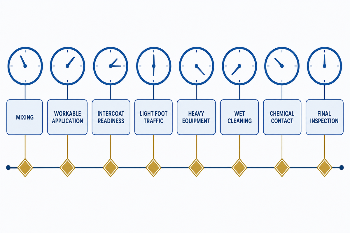
Installation control should follow the current product instruction and approved method, not a generic resin recipe. Confirm the identity and batch condition, mix ratio, equipment used, mixing sequence, working time, application range, applied-layer consumption, surface condition, recoat state and environmental limits. For a jurisdiction-scoped example, 29 CFR 1915.35 separates ventilation, vapour testing and ignition control during coating application. Log the actual conditions and decisions for each work front rather than filling out a completed form with target values.
One “cure time” field isn’t sufficient. A system can have separate clocks for mixing, workable application, intercoat readiness, light foot traffic, heavy equipment, wet cleaning, chemical contact and final inspection. Some clocks are temperature and/or humidity dependent; some require a specific physical condition or approval. The schedule must state which clock controls each release.
Confirm each layer prior to covering, exclude dust and adjacent trade contamination, and record delays or treatment that alters the recoat route. Missed conditions require an authorized disposition; the next layer doesn’t nullify the exception.
Evidence capsule: An illustrative log may show 20°C, 68% relative humidity, a 12-minute mix start, a 35-minute application period and a 16-hour recoat check. None is a recommended target. Each value must be judged against the named product, layer, condition and approved method.
Use a Hidden-Layer Evidence Index
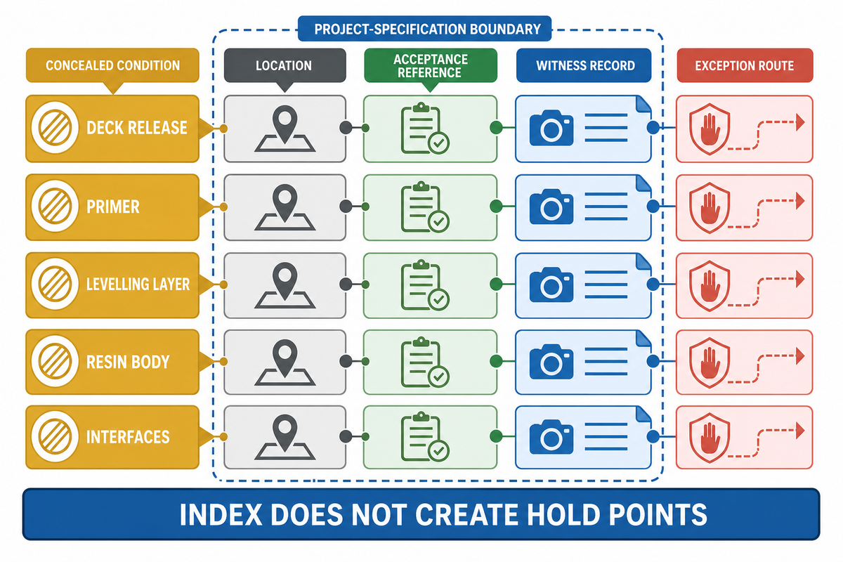
The Hidden-Layer Evidence Index is an editorial project record of what must be observed before the next layer conceals it. It indexes the witness, location, acceptance reference, record type and exception route for each concealed stage. The project specification and responsible parties must define inspection hold points; this index neither creates them nor substitutes for an approved inspection plan. A resource to organize resin-floor project records can help teams structure those records without changing their approval status.
| Stage | What becomes hidden | Witness question | Minimum record fields | Exception route |
|---|---|---|---|---|
| Deck release | Original deck condition | Does it match the accepted substrate basis? | Grid, drawing, condition, date, witness | Clean, repair or engineering review |
| Prepared surface | Preparation and cleanliness | Was the specified condition observed? | Area, method, result and release | Reprepare and reinspect |
| Primer | Deck-to-system interface | Correct product, batch and coverage? | Batch, start, finish and observation | Supplier-approved disposition |
| Levelling layer | Geometry and intermediate bond | Correct profile and readiness? | Grid, check, result and acceptance | Repair before resin body |
| Joint detail | Movement accommodation | Does construction match the joint detail? | Joint ID, photo, revision and witness | Stop and coordinate |
| Drain detail | Edge, slope and service interface | Is the drain released by all trades? | Drain ID, level, detail and parties | Reopen the interface action |
| Penetration | Cut edge and seal relationship | Is the approved collar or closure present? | Service ID, detail, photo and release | Coordinate before closure |
| Resin body | Mix and layer history | Do batch and workfront records align? | Batch, times, conditions and area | Quarantine affected area |
| Texture or broadcast | Distribution beneath seal | Is the required condition uniform? | Area, method, observation and photo | Correct before topcoat |
| Pre-topcoat release | Whole intermediate construction | Are open exceptions closed? | Punch list, status, witness and release | No covering until closure |
ASTM D8555-24 describes qualitative acoustical sounding for potential coating or lining detachment, with interpretation limits. That method cannot recreate preparation, mixing, atmosphere or timing records. Investigation of condition and process traceability provides different answers.
Evidence capsule: A useful witness record links a 14 m² workfront, 3 batches, 2 drain details and a 45-minute inspection window to the current drawing revision. The counts are an example format; the project decides the actual lot and witness boundaries.
Accept the Installed Floor With Scoped Evidence
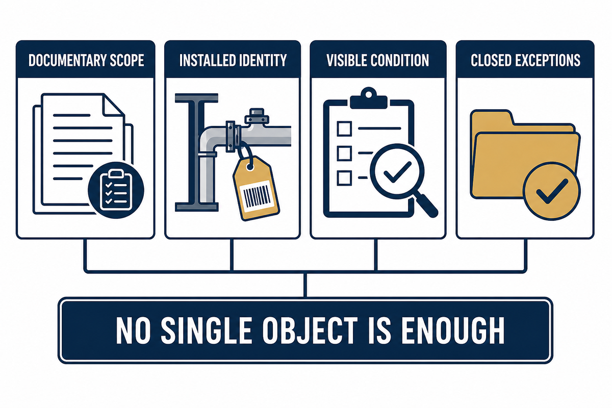
Acceptance should be reconciled with the documented scope, installed identity, and visible condition, and closed exceptions. Review the current construction and approval basis, material and batch traceability, workfront records, hidden-layer witnesses, environmental and timing logs, interface releases, repairs and final observations. No single certificate, test or visual walkdown satisfies all of those requirements.
Write the acceptance plan before installing. Identify in the plan documents that are for information, documents that require review and approvals, stages with witness or hold points, who can release them, and the closure of nonconformities. ASTM D3276-21’s public scope reinforces the general principle that inspection requirements belong in the coating or lining specification rather than being invented at final inspection.
Keep traction claims within their method, specimen, contaminant and preparation conditions. Examine defects, edges, ponding paths, textures, and transitions under agreed upon conditions. Visual acceptance isn’t a means to certify preparation that hasn’t been observed or to extend a report beyond its specimen.
Evidence capsule: A closeout schedule can require 100% of named drains, 12 interface details, 4 repair locations and a 48-hour observation point. Those quantities must reflect the approved inspection plan; they are not universal acceptance frequencies or cure requirements.
Preserve Evidence Before Diagnosing a Visible Defect
A defect is a symptom and not a definitive diagnosis. First preserve its location, size, shape, timing, service condition, cleaning history, nearby interfaces and construction records; then compare plausible causes through record review and targeted checks, while ASTM D8555-24 acoustic sounding can only screen for potential detachment within its interpretive limits. Evidence can be easily lost if the floor is opened. One shouldn’t attempt to identify one possible cause from a photograph as this can result in the repair being misguided.
| Observation | Competing explanations | Preserve first | Discriminating check | Repair decision waits for |
|---|---|---|---|---|
| Bubble or blister | Entrapped gas, moisture, mix or timing issue | Map, cross-section location and batch history | Targeted examination and record review | Cause and affected boundary |
| Delamination | Substrate, intercoat, contamination or movement | Failure plane and surrounding sound area | Locate the separation plane | Interface-specific cause |
| Crack | Deck, joint, layer shrinkage, impact or movement | Ends, width, direction and structural context | Compare with deck and joint records | Active or stable classification |
| Soft or uncured area | Mix, ratio, contamination, temperature or material | Batch, tools, conditions and boundaries | Supplier-directed examination | Affected lot and safe removal plan |
| Colour variation | Batch, application, exposure or repair edge | Lighting, batch and workfront sequence | View under agreed conditions | Aesthetic versus service effect |
| Local wear | Traffic, cleaning, spill, impact or low build | Route, tools, frequency and layer history | Compare adjacent exposure zones | Controlling service mechanism |
| Slippery complaint | Contaminant, cleaning residue, footwear or texture | Wet state, soil, task and cleaning event | Relevant condition-specific assessment | Operating condition definition |
| Edge lifting | Impact, water path, preparation or detail | Edge construction and nearby service | Trace the boundary and failure plane | Dry and stable repair substrate |
| Drain-area damage | Geometry, ponding, cleaning or trade interface | Drain detail, levels and service history | Joint inspection with affected trades | Coordinated drain repair |
Do
- Quarantine the bounded area and tie photographs to a grid.
- Retain samples and batch records under an agreed chain of custody.
- Test one hypothesis at a time and record why each check was chosen.
Don’t
- Assign cause from appearance alone.
- Spread a repair beyond the evidenced boundary without review.
- Cover the failure plane before responsible parties record it.
Plan Cleaning, Repair and Refit Before Handover
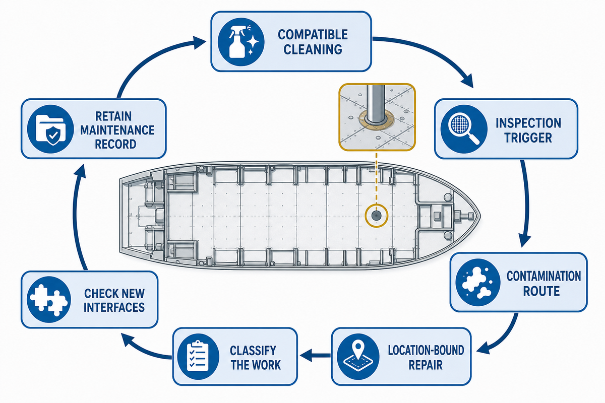
The service soil, cleaning process, texture, drainage, traffic and repair access should form the basis of the maintenance plan. Give the crew compatible cleaning instructions, inspection triggers and a route for uncertain contamination. Observations, nonconformities, corrective actions and maintenance records should be related to the vessel’s applicable maintenance system, and the floor should not be left as an isolated handover leaflet.
Housekeeping starts during installation. United States rule 29 CFR 1915.81 refers to slippage, access, waste management, and as much as practical, working surfaces that are dry. It doesn’t provide a selection for resin floors. It illustrates that the work-area condition is a live production control.
Repairs are expected to restore the required layers and interface functions, and not only appearance. Record the failure plane, contamination removal, preparation, compatible repair build-up, overlap or edge geometry, witness stage and return-to-use basis. If the original chemistry or service is questionable, don’t assume that a resin layer will bond to an unknown surface. In these cases, it’s prudent to check for compatibility.
A refit can alter the compliance question. Consider and classify what work is being done before establishing a baseline. Then check new penetrations, drains, thresholds, equipment bases and adjacent finishes. A subsequent cut may cross the approved construction, or even create a new route for water and contamination, even though most of the original floor is still intact.
Evidence capsule: A maintenance record could map a 0.4 m² patch, a 2 m perimeter, 3 cleaning events and a 7-day observation period. These values describe a record format only. The approved repair method and vessel plan determine the real area, overlap, products and release timing.
Build a Handover and Request-for-Quotation Pack
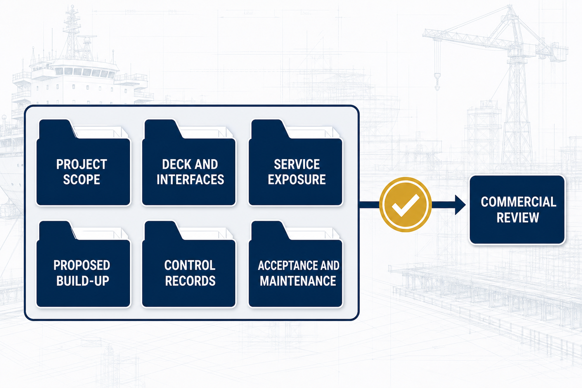
The goal is to design a handover and request-for-quotation pack that allows each bidder to price the same work scope and allows the yard to trace the accepted construction later. It should incorporate the compartment schedule, layer build-up, interfaces, approval questions, installation controls, witness records and maintenance requirements. Missing inputs should have named owners and due dates, instead of being hidden in the “to be confirmed” section. For preliminary load planning, the resin floor layer-mass tool can organize assumptions before the named build-up is confirmed.
Prepare these items before asking for a commercial configuration:
- vessel type, build or refit status, flag, voyage and governing project rules;
- compartment list, areas, steel-deck condition and retained coatings;
- service water, chemicals, oils, temperature, traffic, impact, cleaning and drainage;
- height, weight, level, transition and structural movement constraints;
- drain, joint, cove, threshold, penetration and equipment-base details;
- available shutdown, ventilation, exclusion, environmental control and return-to-use sequence;
- required product, test, approval, drawing, traceability and inspection evidence;
- witness, hold-point, nonconformance, repair and change-control responsibilities; and
- as-built dossier, cleaning plan, repair method and maintenance-system inputs.
Those who have assembled this neutral project brief can now compare Yibo resin build-ups. That solution page owns flooring system product configurations, technical data, approval documents and solutions for quotation. This article stays on the informational side: how to select, control, inspect, diagnose and hand over a system.
Based on the profile supplied for this article, Suzhou Yibo Industry & Trade Co., Ltd. was founded in September 2001 in Suzhou, operates on more than 6,000 square metres, supplies several marine floor families, lists ISO 9001:2015 quality-management-system certification and works with named Chinese shipyards. The profile also associates product quality with SOLAS and several classification societies. These attributed statements do not confirm that an unnamed product, assembly or vessel has an active approval or result. Please review the relevant project documents.
Discuss Your Vessel Floor Brief with Yibo
Frequently Asked Questions About Marine Resin Floor Systems
These guidelines frame the decision and do not prescribe an unnamed product. Vessel, compartment, substrate, exposure, safety duties, and the approval pathway are variables that may alter the response. Verify the final build with the concerned parties.
What is a marine resin floor system?
A marine resin floor system is a complete vessel floor build-up that connects the prepared steel deck, primers, levelling layers, resin body, finish, interfaces and documented acceptance route rather than treating resin as an isolated product.
The system can include the steel-deck condition, preparation, primer, levelling or primary layer, resin body, aggregate or texture, topcoat and interface details. Suitability depends on the named space, service duty, application conditions, cleaning plan and evidence route. A finished surface can’t prove the concealed construction, material traceability or scope of an approval record.
Is epoxy or polyurethane better for marine flooring?
Neither epoxy nor polyurethane is universally better for marine flooring; compare two named, complete systems against the same compartment brief, including substrate, exposure, installation access, service readiness, cleaning duty, repairability and evidence requirements.
Check substrate and primer, deck movement, traffic and impact, named chemical contact, wet traction conditions, layer compatibility, application and recoat windows, approval scope, repairability and cleaning duty. Compare the actual formulations and full layer schedules, not selected brochure phrases. Access also matters: a system that can’t be installed, witnessed, protected or repaired within the available shutdown isn’t a resolved choice. Formulations differ within each family, so a generic chemistry table can’t decide the vessel project.
How should a steel deck be prepared for a resin floor?
Prepare a steel deck according to the approved system instructions and project procedure for the actual substrate, retained coating, contamination, corrosion, interfaces, environmental conditions and release criteria; this guide does not prescribe one universal surface profile.
Map the substrate, contamination, corrosion, welds, joints, drains, penetrations and neighbouring work. Define preparation, cleanliness, environmental and release criteria, then record the observed condition by location and drawing revision. This guide gives no universal profile or moisture limit because the correct requirement belongs to the named product, deck condition and project.
Does a type-approval certificate prove that the installed floor is accepted?
No. A type-approval certificate establishes only its stated scope and limits; installed-floor acceptance also requires the applicable vessel and compartment basis, construction match, material traceability, inspection records, closed exceptions and responsible-party review.
Match the installed build-up to the applicable record and governing regime. Trace and acceptance records remain necessary.
What records should be kept during installation?
Keep location-linked installation records for substrate release, material and batch identity, environmental conditions, mixing, layer application and readiness, drains, penetrations, interfaces, witnesses, nonconformities, bounded repairs, reinspection and final acceptance.
Connect each record to a compartment or grid and the current drawing revision. Include material and batch identity, expiry where relevant, workfront start and finish, environmental readings required by the procedure, mix and layer releases, drain and penetration details, photographs, responsible witnesses and open actions. Record nonconformance dispositions, bounded repairs, reinspection and final acceptance. A folder of unlocated photographs can’t show where reviewed work occurred, which revision applied or whether an exception was closed before covering.
Conclusion
Marine resin floor selection is an evidence-led project process. Define exposure, access and evidence. Compare complete build-ups. Separate approval from vessel acceptance. Map the interfaces. Control the readiness clocks. Witness hidden layers and preserve defect evidence before they are covered. The dossier supports procurement, production, inspection, maintenance and refit without asking one label or certificate to prove too much.
References & Sources
- Approved Finish Materials and Primary Deck Coverings United States Coast Guard
- 46 CFR Subpart 164.006: Deck Coverings for Merchant Vessels Electronic Code of Federal Regulations
- 29 CFR 1915.35: Painting Electronic Code of Federal Regulations
- History of Fire Protection Requirements International Maritime Organization
- ASTM D3276-21: Painting Inspectors for Metal Substrates ASTM International
- ASTM D8555-24: Acoustical Sounding of Coatings and Linings ASTM International
- The Two Pillars of Surface Preparation American Coatings Association
- Thoughts on Maintenance Coatings American Coatings Association



![Marine PU Floor: Selection & Installation [Guide]](https://yibomarine.com/wp-content/uploads/2026/09/marine-pu-floor-blog-featured-150x150.png)